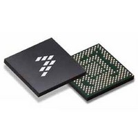
SC900841JVKR2 Freescale Semiconductor, SC900841JVKR2 Datasheet - Page 116

SC900841JVKR2
Manufacturer Part Number
SC900841JVKR2
Description
IC POWER MGT 338-MAPBGA
Manufacturer
Freescale Semiconductor
Specifications of SC900841JVKR2
Applications
PC's, PDA's
Operating Temperature
-40°C ~ 85°C
Mounting Type
Surface Mount
Package / Case
338-TBGA
Input Voltage
2.8 V to 4.4 V
Maximum Operating Temperature
+ 85 C
Minimum Operating Temperature
- 40 C
Lead Free Status / RoHS Status
Lead free / RoHS Compliant
Current - Supply
-
Voltage - Supply
-
Lead Free Status / Rohs Status
Lead free / RoHS Compliant
Available stocks
Company
Part Number
Manufacturer
Quantity
Price
Company:
Part Number:
SC900841JVKR2
Manufacturer:
Freescale Semiconductor
Quantity:
10 000
- Current page: 116 of 192
- Download datasheet (8Mb)
Table 73. Extended Backlight Control Registers Structure and Bits Description
CAMERA SCENE ILLUMINATION CURRENT
DRIVER
Camera Scene Illumination. The string is powered from the
VBKLT boost regulator. The brightness control is done
through a 3-bit PWM duty cycle control with fixed PWM
frequency.
SIGNALING/STATUS LED DRIVERS
form of two banks of RGB LED drivers. The signaling LED
drivers LEDR1, LEDG1, LEDB1, LEDR2, LEDG2, and
LEDB2 are independent current sink channels. Each driver
channel features programmable current levels via
LEDxBRT[1:0] as well as programmable PWM duty cycle
settings with LEDxDC[5:0]. By a combination of level and
PWM settings, each channel provides flexible LED intensity
control. By driving LEDs of different colors, color mixing can
be achieved. The default duty cycle, when a blink period is
set, not continuous, is 0.5 s on time.
than red and normal green signal LEDs. In the application, a
5.0 V or equivalent supply rail is therefore required. This is
provided by the integrated 5.0 V boost converter VOTG.
116
900841
Table 74. Camera String Illumination Control Register Structure and Bits Description
FUNCTIONAL DEVICE OPERATION
LIGHTING SYSTEM
FSL4STRING (ADDR 0x1D4 - R/W - Default Value: 0x00)
BKLTBRTL2
FSLVBKLTADAPT (ADDR 0x1D5 - R/W - Default Value: 0x00)
S4ADAPT
Reserved
TWOPTWO
The 900841 supports one string of up to 5-6 LEDs for
The 900841 contains signaling/status LED drivers in the
Blue LEDs or bright green LEDs require more headroom
Reserved
SILTBRT
SLEDEN
Name
7:0
0
7:1
7
Bits
3:1
7:4
0
Independent Zone (Backlight) Configuration Enable
x0 = Independent Zone Backlighting Option is disabled (Default)
x1 = Independent Zone Backlighting Option is Enabled
LCD Backlight PWM Duty Cycle Settings for string 4 in single backlight configuration or for Strings 3-4 for independent
zone backlight configuration. See
Enable String 4 to be part of the adaptive boost control
x0 = Disable (Default)
x1 = Enable
Reserved
Camera Scene Illumination Drivers Enable Bit
x0 = Disable
x1 = Enable
Camera Scene Illumination PWM Duty Cycle Settings
x0 = 12.5%
x1 = 25%
x2 = 37.5%
x3 = 50%
Reserved
SSTRING (ADDR 0x2B - R/W - Default Value: 0x00)
Table 70
for Duty Cycle Settings
backlight support, see VBKLT, in which case it is controlled
like the other LCD backlight strings, see
Drivers.
Camera Scene Illumination Drivers Status/Control
Registers and Bits Description
Battery voltage can also be used to supply the RGB banks
directly via VPWR, if enough headroom is possible, by using
low forward voltage LEDs. Furthermore, each one of these
drivers can be supplied from a different source, as they are
completely independent. The PWM waveforms are
staggered from each other by one cycle of 32 kHz to
minimize sudden load changes on the LED supply.
patterns implemented in hardware. Ramp patterns for each
of the drivers are accessed with the corresponding
LEDxRAMP bit. The ramp itself is generated by increasing or
decreasing the PWM duty cycle with a 1/32 step every 1/64
seconds. The ramp time is therefore a function of the initial
set PWM cycle and the final PWM cycle. As an example,
starting from 0/32 and going to 32/32 will take 500 ms, while
going to from 8/32 to 16/32 takes 125 ms. Note that the ramp
function is executed upon every change in PWM cycle
This string can also be used as an additional string for
The signaling LED drivers include ramp up and ramp down
Description
x4 = 62.5%
x5 = 75%
x6 = 87.5%
x7 = 100%
Analog Integrated Circuit Device Data
Freescale Semiconductor
LCD Backlight
Related parts for SC900841JVKR2
Image
Part Number
Description
Manufacturer
Datasheet
Request
R
Part Number:
Description:
Ultra-mobile Platform Pmic
Manufacturer:
Freescale Semiconductor, Inc
Datasheet:

Part Number:
Description:
Sc900 Programmable Penta Uldo With Reset And I2c Interface
Manufacturer:
Semtech Corporation
Datasheet:
Part Number:
Description:
Manufacturer:
Freescale Semiconductor, Inc
Datasheet:
Part Number:
Description:
Manufacturer:
Freescale Semiconductor, Inc
Datasheet:
Part Number:
Description:
Manufacturer:
Freescale Semiconductor, Inc
Datasheet:
Part Number:
Description:
Manufacturer:
Freescale Semiconductor, Inc
Datasheet:
Part Number:
Description:
Manufacturer:
Freescale Semiconductor, Inc
Datasheet:
Part Number:
Description:
Manufacturer:
Freescale Semiconductor, Inc
Datasheet:
Part Number:
Description:
Manufacturer:
Freescale Semiconductor, Inc
Datasheet:
Part Number:
Description:
Manufacturer:
Freescale Semiconductor, Inc
Datasheet:
Part Number:
Description:
Manufacturer:
Freescale Semiconductor, Inc
Datasheet:
Part Number:
Description:
Manufacturer:
Freescale Semiconductor, Inc
Datasheet:
Part Number:
Description:
Manufacturer:
Freescale Semiconductor, Inc
Datasheet:
Part Number:
Description:
Manufacturer:
Freescale Semiconductor, Inc
Datasheet:
Part Number:
Description:
Manufacturer:
Freescale Semiconductor, Inc
Datasheet:


