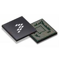
SC900841JVKR2 Freescale Semiconductor, SC900841JVKR2 Datasheet - Page 163

SC900841JVKR2
Manufacturer Part Number
SC900841JVKR2
Description
IC POWER MGT 338-MAPBGA
Manufacturer
Freescale Semiconductor
Specifications of SC900841JVKR2
Applications
PC's, PDA's
Operating Temperature
-40°C ~ 85°C
Mounting Type
Surface Mount
Package / Case
338-TBGA
Input Voltage
2.8 V to 4.4 V
Maximum Operating Temperature
+ 85 C
Minimum Operating Temperature
- 40 C
Lead Free Status / RoHS Status
Lead free / RoHS Compliant
Current - Supply
-
Voltage - Supply
-
Lead Free Status / Rohs Status
Lead free / RoHS Compliant
Available stocks
Company
Part Number
Manufacturer
Quantity
Price
Company:
Part Number:
SC900841JVKR2
Manufacturer:
Freescale Semiconductor
Quantity:
10 000
- Current page: 163 of 192
- Download datasheet (8Mb)
PENDETEN bit in the ADCCNTL1 register. When this bit is
enabled and a pen touch is detected, the PENDET bit in
register ADCINT is set and the PMICINT pin is asserted. This
is to interrupt the system, because a touch screen pen touch
has been detected at the next ADC cycle, unless the interrupt
is masked.
TSREF and is powered from VCORE. In touch screen
operation, TSREF is a dedicated regulator. No loads other
than the touch screen should be connected here. When the
ADC performs non touch screen conversions, the ADC does
not rely on TSREF and the reference can be disabled.
BATTERY COULOMB COUNTER
OVERVIEW
through the general purpose ADC as a voltage drop over the
RCC sense resistor, see
voltage reading, the battery capacity can be estimated. More
Analog Integrated Circuit Device Data
Freescale Semiconductor
Table 108. Touch Screen System Requirements
Plate Resistance X, Y
Resistance Between Plates, Contact
Capacitance Between Plates
Contact Resistance Current Source
Interrupt Current Source
Interrupt Threshold
Current Source Inaccuracy
Quiescent Current (Active Mode)
Max Load Current (Active Mode)
Settling Time (Position Measurement)
Touch Screen Pen detection bias can be enabled via the
The prior reference for the touch screen (Touch Bias) is
The current into and from the battery can be read out
Figure
77.
Together with the battery
Figure 76. Touch Screen Configuration Example
resistances are of no influence to the overall readout. The
readout scheme does not account for contact resistances, as
present in the touch screen connectors. Therefore, the touch
screen readings have to be calibrated by the user or in the
factory, where one has to point with a stylus to the opposite
corners of the screen. When reading out the X-coordinate,
the 10-bit ADC reading represents a 10-bit coordinate with '0'
for a coordinate equal to X- and full scale '1023' when equal
to X+. When reading out the Y-coordinate, the 10-bit ADC
reading represents a 10-bit coordinate with '0' for a
coordinate equal to Y- and full scale '1023' when equal to Y+.
When reading the contact resistance the 10-bit ADC reading
represents the voltage drop over the contact resistance
created by the known current source multiplied by 2.
accurate battery capacity estimation can be obtained by
using the integrated Coulomb Counter.
in/out of the battery by integrating the voltage drop across the
battery current sense resistor RCC, followed by an A to D
conversion. The result of the A to D conversion is used to
increase/decrease the contents of an internal counter
CCOUT[15:0]. This counter can be read out by software on
The readouts are designed such that the on chip switch
The Coulomb Counter (or CC) monitors the current flowing
-
-
-
-
-
-
-
-
100
180
0.5
3.0
40
-
-
-
-
-
FUNCTIONAL DEVICE OPERATION
100
20
20
2
-
-
-
-
-
-
ADC SUBSYSTEM
1000
1200
5.5
60
20
20
-
-
-
-
mA
μ A
μ A
k Ω
μ A
nF
μ s
900841
Ω
Ω
%
163
Related parts for SC900841JVKR2
Image
Part Number
Description
Manufacturer
Datasheet
Request
R
Part Number:
Description:
Ultra-mobile Platform Pmic
Manufacturer:
Freescale Semiconductor, Inc
Datasheet:

Part Number:
Description:
Sc900 Programmable Penta Uldo With Reset And I2c Interface
Manufacturer:
Semtech Corporation
Datasheet:
Part Number:
Description:
Manufacturer:
Freescale Semiconductor, Inc
Datasheet:
Part Number:
Description:
Manufacturer:
Freescale Semiconductor, Inc
Datasheet:
Part Number:
Description:
Manufacturer:
Freescale Semiconductor, Inc
Datasheet:
Part Number:
Description:
Manufacturer:
Freescale Semiconductor, Inc
Datasheet:
Part Number:
Description:
Manufacturer:
Freescale Semiconductor, Inc
Datasheet:
Part Number:
Description:
Manufacturer:
Freescale Semiconductor, Inc
Datasheet:
Part Number:
Description:
Manufacturer:
Freescale Semiconductor, Inc
Datasheet:
Part Number:
Description:
Manufacturer:
Freescale Semiconductor, Inc
Datasheet:
Part Number:
Description:
Manufacturer:
Freescale Semiconductor, Inc
Datasheet:
Part Number:
Description:
Manufacturer:
Freescale Semiconductor, Inc
Datasheet:
Part Number:
Description:
Manufacturer:
Freescale Semiconductor, Inc
Datasheet:
Part Number:
Description:
Manufacturer:
Freescale Semiconductor, Inc
Datasheet:
Part Number:
Description:
Manufacturer:
Freescale Semiconductor, Inc
Datasheet:


