SC900841JVKR2 Freescale Semiconductor, SC900841JVKR2 Datasheet - Page 124
SC900841JVKR2
Manufacturer Part Number
SC900841JVKR2
Description
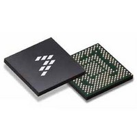
IC POWER MGT 338-MAPBGA
Manufacturer
Freescale Semiconductor
Specifications of SC900841JVKR2
Applications
PC's, PDA's
Operating Temperature
-40°C ~ 85°C
Mounting Type
Surface Mount
Package / Case
338-TBGA
Input Voltage
2.8 V to 4.4 V
Maximum Operating Temperature
+ 85 C
Minimum Operating Temperature
- 40 C
Lead Free Status / RoHS Status
Lead free / RoHS Compliant
Current - Supply
-
Voltage - Supply
-
Lead Free Status / Rohs Status
Lead free / RoHS Compliant
Available stocks
Company
Part Number
Manufacturer
Quantity
Price
Company:

Part Number:
SC900841JVKR2
Manufacturer:
Freescale Semiconductor
Quantity:
10 000


in 100% Duty Cycle mode, the output current limit is still
operational.
sensing the voltage across R
charger system to regulate the power draw out of the input
adaptor to fit the needs of the system. During charging, if an
input source is connected and the selected charging current
plus load current exceeds the current limit set by the
USBLMT[1:0] bits and detected across R
charger buck will behave like a constant current source,
supplying the current limit. The V
the DCLMT interrupt signal is asserted. As the V
approaches the V
M
maintain the programmed charge current. At some point, the
charge current will start to decrease, as this current starts to
get limited by the R
stabilize at a point where the charge current equates to the
difference between the input current limit set by
USBLMT[1:0] and the total system load current. If the load
current by itself exceeds the input current limit, the V
voltage will fall more below the V
current will come from the battery through M
fully switched on in this instance. The USBLMT settings are
maximum numbers and will not be exceeded, so a lower
value should be targeted as a typical and ±5% accuracy is
desired
discharged, M
the series resistance between V
overall system efficiency and battery life. The system can
activate this function by asserting the CHGBYP bit high. So if
CHGBYP is “1”, and whenever V
100 mV, the 900841 turns on MCHGBYP. If CHGBYP is “0”,
this function is deactivated. If MCHGBYP is not used, the
CHGBYPGT pin must be connected to ground.
charger buck monitors the voltage at the RAWCHG pin. If
V
detected, the over-voltage protection FET M
disabled, the charger buck is disabled, and the USBOVP
interrupt signal is asserted and the RDSTATE register is
updated to state 0x02 (AC Adaptor OVP). Such over-voltage
condition can occur due to a faulty USB/AC adapter design or
a voltage spike during the insertion of the adapter to the
system. Input over-voltage protection is an optional feature,
as there are other methods to prevent an over-voltage
condition. Such methods, like a Zener clamp, can limit the
input voltage to a 6.0 V maximum, under which case
M
performance or well designed adaptor that can guarantee a
maximum input voltage of 5.5 V, will eliminate the need for
M
occur to the IC. Without the presence of M
maximum voltage will be exceeded for many parts of the IC.
supply power to the VPWR node through the charger pass
124
900841
FUNCTIONAL DEVICE OPERATION
BATTERY INTERFACE AND POWER PATH MANAGEMENT
RAWCHG
CHG
OVPCHG
OVPCHG
The charger buck monitors the input current draw by
In the previous case, where the battery is being
To prevent an over-voltage condition to the system, the
Whenever the charger buck is disabled, the battery will
, will switch itself fully on as the charger control tries to
. If any of these other methods fail, damage will
rises above 5.75 V, an over-voltage condition is
is not needed and can be removed. Using a high
CHGBYP
BAT
ds(on)
voltage, the charger pass transistor,
provides an optional feature to reduce
of M
INSNSCHG
CHG
BAT
BAT
PWR
PWR
. The V
and V
voltage, and the excess
voltage will droop, and
falls below V
which will allow the
PWR
INSNSCHG
PWR
OVPCHG
CHG
OVPCHG
voltage will
, saving on
, which is still
PWR
, a
BAT
, the
voltage
PWR
is
by
transistor element M
In that case, M
isolate the input power connector from the battery and
prevent reverse current draw from battery to connector. For
lower power inputs, like a dedicated USB source, M
can be replaced by a low forward voltage drop Schottky
Diode, pointing the same direction as the M
diode. In this case, REVPCHGGT should be grounded. No
specific Schottky diode is recommended. Any 2.0 A/30 V
capable diode with low forward voltage drop can use used.
and M
In this case, V
depending on the value of the battery, as explained in the first
paragraph. Reference
information.
LI-ION BATTERY CHARGER
FEATURES
• Complete charger for single-cell Li-Ion batteries with an
• Programmable constant charge current limit (I
• Programmable End-of-Charge (EOC) detection current
• Programmable trickle charge current (I
• Intelligent EOC detection to prevent false indication
• Programmable battery float voltage (V
• Programmable battery over-voltage (V
• Optional battery temperature monitoring NTC thermistor
• Ability for trickle mode only charging
• Programmable smart timer for charge termination and
• Programmable battery over-voltage protection
• Intelligent Interrupt and State reporting capabilities
Charger Operation
Constant Voltage (CC/CV) charging output with the
preconditioning function (trickle charge) for deeply
discharged batteries. Multiple parameters can be
programmed through the SPI registers.
its input and V
headroom of 300 mV across it, V
maximum charging current flowing into the battery (I
to the value set by SPI programming of the CHRGCC[2:0]
bits. The 300 mV headroom includes the voltage drop across
R
resistor R
a maximum constant current equal to I
value of R
SNSBAT
The system can assert the BATISO bit to turn off M
external PFET pass element
(I
interface for charge qualification with two different
temperature ranges for charging and discharging
detection of fault conditions (t
The charger provides the traditional Constant Current/
The charger is a Constant Current Regulator with V
The loop will regulate the voltage drop over the sense
CHGCOMP
CHGBYP
and R
SNSBAT
SNSBAT
)
PWR
if used, to isolate the battery from the system.
BAT
REVPCHG
CC
by controlling M
influences the charge current, and its
.
as its output, with constant voltage
has to be higher than V
CHG
Analog Integrated Circuit Device Data
Power States and Control
, and also through M
switch is disabled to electrically
CHG
PWR
CHG
Freescale Semiconductor
)
– V
to a value resulting in
CHGCC
BAT
CHGCV
OVRVOLT
TRKL
BAT
REVPCHG
. It regulates the
CHGBYP
. Therefore, the
)
and set,
)
CHGCC
for more
)
REVPCHG
CHGCC
if used.
PWR
body
CHG
)
as
,
)
,
Related parts for SC900841JVKR2
Image
Part Number
Description
Manufacturer
Datasheet
Request
R

Part Number:
Description:
Ultra-mobile Platform Pmic
Manufacturer:
Freescale Semiconductor, Inc
Datasheet:

Part Number:
Description:
Sc900 Programmable Penta Uldo With Reset And I2c Interface
Manufacturer:
Semtech Corporation
Datasheet:
Part Number:
Description:
Manufacturer:
Freescale Semiconductor, Inc
Datasheet:
Part Number:
Description:
Manufacturer:
Freescale Semiconductor, Inc
Datasheet:
Part Number:
Description:
Manufacturer:
Freescale Semiconductor, Inc
Datasheet:
Part Number:
Description:
Manufacturer:
Freescale Semiconductor, Inc
Datasheet:
Part Number:
Description:
Manufacturer:
Freescale Semiconductor, Inc
Datasheet:
Part Number:
Description:
Manufacturer:
Freescale Semiconductor, Inc
Datasheet:
Part Number:
Description:
Manufacturer:
Freescale Semiconductor, Inc
Datasheet:
Part Number:
Description:
Manufacturer:
Freescale Semiconductor, Inc
Datasheet:
Part Number:
Description:
Manufacturer:
Freescale Semiconductor, Inc
Datasheet:
Part Number:
Description:
Manufacturer:
Freescale Semiconductor, Inc
Datasheet:
Part Number:
Description:
Manufacturer:
Freescale Semiconductor, Inc
Datasheet:
Part Number:
Description:
Manufacturer:
Freescale Semiconductor, Inc
Datasheet:
Part Number:
Description:
Manufacturer:
Freescale Semiconductor, Inc
Datasheet: