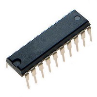
MCHC705JJ7CPE Freescale Semiconductor, MCHC705JJ7CPE Datasheet - Page 71

MCHC705JJ7CPE
Manufacturer Part Number
MCHC705JJ7CPE
Description
IC MCU 8BIT 224 BYTES RAM 20PDIP
Manufacturer
Freescale Semiconductor
Series
HC05r
Datasheet
1.MC705JJ7CDWE.pdf
(164 pages)
Specifications of MCHC705JJ7CPE
Core Processor
HC05
Core Size
8-Bit
Speed
2.1MHz
Connectivity
SIO
Peripherals
POR, Temp Sensor, WDT
Number Of I /o
14
Program Memory Size
6KB (6K x 8)
Program Memory Type
OTP
Ram Size
224 x 8
Voltage - Supply (vcc/vdd)
2.7 V ~ 5.5 V
Data Converters
A/D 4x12b
Oscillator Type
Internal
Operating Temperature
-40°C ~ 85°C
Package / Case
20-DIP (0.300", 7.62mm)
Processor Series
HC705JJ
Core
HC05
Data Bus Width
8 bit
Data Ram Size
224 B
Interface Type
SIOP
Maximum Clock Frequency
2.1 MHz
Number Of Programmable I/os
14
Number Of Timers
2
Maximum Operating Temperature
+ 85 C
Mounting Style
Through Hole
Minimum Operating Temperature
- 40 C
On-chip Adc
12 bit, 4 Channel
Package
20PDIP
Family Name
HC05
Maximum Speed
2.1 MHz
Operating Supply Voltage
3.3|5 V
Lead Free Status / RoHS Status
Lead free / RoHS Compliant
Eeprom Size
-
Lead Free Status / Rohs Status
Details
- Current page: 71 of 164
- Download datasheet (2Mb)
Chapter 8
Analog Subsystem
8.1 Introduction
The analog subsystem of the MC68HC705JJ7/MC68HC705P7 is based on two on-chip voltage
comparators and a selectable current charge/discharge function as shown in
This configuration provides several features:
Voltages are resolved by measuring the time it takes an external capacitor to charge up to the level of the
unknown input voltage being measured. The beginning of the A/D conversion time can be started by
several means:
The end of the A/D conversion time can be captured by these means:
Freescale Semiconductor
•
•
•
•
•
•
•
•
Two independent voltage comparators with external access to both inverting and non-inverting
inputs
One voltage comparator can be connected as a single-slope analog-to-digital (A/D) and the other
connected as a single-voltage comparator. The possible single-slope A/D connection provides
these features:
–
–
–
–
–
–
–
Output compare from the 16-bit programmable timer
Timer overflow from the 16-bit programmable timer
Direct software control via a register bit
Input capture in the 16-bit programmable timer
Interrupt generated by the comparator output
Software polling of the comparator output using software loop time
A/D conversions can use V
calculate ratiometric or absolute results
Channel access of up to four inputs via multiplexer control with independent multiplexer control
allowing mixed input connections
Access to V
Divide by 2 to extend input voltage range
Each comparator can be inverted to calculate input offsets.
Internal sample and hold capacitor
Direct digital output of comparator 1 to the PB4 pin
MC68HC705JJ7 • MC68HC705JP7 Advance Information Data Sheet, Rev. 4.1
DD
and V
SS
for calibration
DD
or an external voltage as a reference with software used to
Figure
8-1.
71
Related parts for MCHC705JJ7CPE
Image
Part Number
Description
Manufacturer
Datasheet
Request
R
Part Number:
Description:
Manufacturer:
Freescale Semiconductor, Inc
Datasheet:
Part Number:
Description:
Manufacturer:
Freescale Semiconductor, Inc
Datasheet:
Part Number:
Description:
Manufacturer:
Freescale Semiconductor, Inc
Datasheet:
Part Number:
Description:
Manufacturer:
Freescale Semiconductor, Inc
Datasheet:
Part Number:
Description:
Manufacturer:
Freescale Semiconductor, Inc
Datasheet:
Part Number:
Description:
Manufacturer:
Freescale Semiconductor, Inc
Datasheet:
Part Number:
Description:
Manufacturer:
Freescale Semiconductor, Inc
Datasheet:
Part Number:
Description:
Manufacturer:
Freescale Semiconductor, Inc
Datasheet:
Part Number:
Description:
Manufacturer:
Freescale Semiconductor, Inc
Datasheet:
Part Number:
Description:
Manufacturer:
Freescale Semiconductor, Inc
Datasheet:
Part Number:
Description:
Manufacturer:
Freescale Semiconductor, Inc
Datasheet:
Part Number:
Description:
Manufacturer:
Freescale Semiconductor, Inc
Datasheet:
Part Number:
Description:
Manufacturer:
Freescale Semiconductor, Inc
Datasheet:
Part Number:
Description:
Manufacturer:
Freescale Semiconductor, Inc
Datasheet:
Part Number:
Description:
Manufacturer:
Freescale Semiconductor, Inc
Datasheet:


