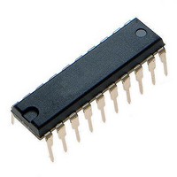
MCHC705JJ7CPE Freescale Semiconductor, MCHC705JJ7CPE Datasheet - Page 38

MCHC705JJ7CPE
Manufacturer Part Number
MCHC705JJ7CPE
Description
IC MCU 8BIT 224 BYTES RAM 20PDIP
Manufacturer
Freescale Semiconductor
Series
HC05r
Datasheet
1.MC705JJ7CDWE.pdf
(164 pages)
Specifications of MCHC705JJ7CPE
Core Processor
HC05
Core Size
8-Bit
Speed
2.1MHz
Connectivity
SIO
Peripherals
POR, Temp Sensor, WDT
Number Of I /o
14
Program Memory Size
6KB (6K x 8)
Program Memory Type
OTP
Ram Size
224 x 8
Voltage - Supply (vcc/vdd)
2.7 V ~ 5.5 V
Data Converters
A/D 4x12b
Oscillator Type
Internal
Operating Temperature
-40°C ~ 85°C
Package / Case
20-DIP (0.300", 7.62mm)
Processor Series
HC705JJ
Core
HC05
Data Bus Width
8 bit
Data Ram Size
224 B
Interface Type
SIOP
Maximum Clock Frequency
2.1 MHz
Number Of Programmable I/os
14
Number Of Timers
2
Maximum Operating Temperature
+ 85 C
Mounting Style
Through Hole
Minimum Operating Temperature
- 40 C
On-chip Adc
12 bit, 4 Channel
Package
20PDIP
Family Name
HC05
Maximum Speed
2.1 MHz
Operating Supply Voltage
3.3|5 V
Lead Free Status / RoHS Status
Lead free / RoHS Compliant
Eeprom Size
-
Lead Free Status / Rohs Status
Details
Interrupts
With the edge-sensitive only trigger MOR option, a rising edge on a PA0:3 pin latches an external interrupt
request. A subsequent external interrupt request can be latched only after the voltage level of the previous
interrupt signal returns to a logic 0 and then rises again to a logic 1.
4.5.3 IRQ Status and Control Register (ISCR)
The IRQ status and control register (ISCR), shown in
(IRQE), an external interrupt flag (IRQF), and a flag reset bit (IRQR). Unused bits will read as logic 0s.
The ISCR also contains two control bits for the oscillators, external pin oscillator, and internal low-power
oscillator. Reset sets the IRQE and OM2 bits and clears all the other bits.
IRQE — External Interrupt Request Enable Bit
OM1 and OM2 — Oscillator Select Bits
38
This read/write bit enables external interrupts. Reset sets the IRQE bit.
These bits control the selection and enabling of the oscillator source for the MCU. One choice is the
internal low-power oscillator (LPO). The other choice is the external pin oscillator (EPO) which is
common to most M68HC05 MCU devices. The EPO uses external components like filter capacitors
and a crystal or ceramic resonator and consumes more power. The selection and enable conditions
for these two oscillators are shown in
1 = External interrupt processing enabled
0 = External interrupt processing disabled
Address:
If the port A pins are enabled as external interrupts, then a high level on any
PA0:3 pin will drive the state of the IRQ function such that the IRQ/V
and other PA0:3 pins are to be ignored until ALL of the PA0:3 pins have
returned to a low level. Similarly, if the IRQ/V
PA0:3 pins will be ignored until the IRQ/V
Reset:
Read:
Write:
OM2
0
0
1
1
MC68HC705JJ7 • MC68HC705JP7 Advance Information Data Sheet, Rev. 4.1
$000D
IRQE
OM1
Bit 7
Figure 4-4. IRQ Status and Control Register (ISCR)
1
0
1
0
1
= Unimplemented
Oscillator
Selected
OM2
External
by CPU
Internal
Internal
Internal
6
1
Table 4-2. Oscillator Selection
Table
OM1
5
0
Low-Power
Oscillator
Disabled
Internal
Enabled
Enabled
Enabled
4-2.
(LPO)
NOTE
R
R
4
0
0
Figure
PP
= Reserved
IRQF
pin returns to a high state.
External Pin
PP
Oscillator
4-4, contains an external interrupt mask
3
0
Disabled
Disabled
Enabled
Enabled
(EPO)
pin is at a low level, the
2
0
0
Consumption
U = Unaffected
IRQR
Normal
Normal
Lowest
Lowest
Power
U
1
0
PP
Freescale Semiconductor
pin
Bit 0
0
0


