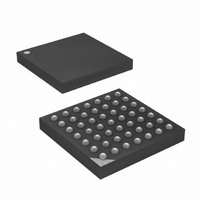
ATXMEGA16A4-CUR Atmel, ATXMEGA16A4-CUR Datasheet - Page 182

ATXMEGA16A4-CUR
Manufacturer Part Number
ATXMEGA16A4-CUR
Description
MCU AVR 16+4KB FLASH 49VFBGA
Manufacturer
Atmel
Series
AVR® XMEGAr
Specifications of ATXMEGA16A4-CUR
Core Processor
AVR
Core Size
8/16-Bit
Speed
32MHz
Connectivity
I²C, IrDA, SPI, UART/USART
Peripherals
Brown-out Detect/Reset, DMA, POR, PWM, WDT
Number Of I /o
34
Program Memory Size
16KB (8K x 16)
Program Memory Type
FLASH
Eeprom Size
1K x 8
Ram Size
2K x 8
Voltage - Supply (vcc/vdd)
1.6 V ~ 3.6 V
Data Converters
A/D 12x12b, D/A 2x12b
Oscillator Type
Internal
Operating Temperature
-40°C ~ 85°C
Package / Case
49-VFBGA
For Use With
ATAVRONEKIT - KIT AVR/AVR32 DEBUGGER/PROGRMMRATSTK600 - DEV KIT FOR AVR/AVR32770-1007 - ISP 4PORT ATMEL AVR MCU SPI/JTAG770-1004 - ISP 4PORT FOR ATMEL AVR MCU SPI
Lead Free Status / RoHS Status
Lead free / RoHS Compliant
Available stocks
Company
Part Number
Manufacturer
Quantity
Price
- Current page: 182 of 445
- Download datasheet (6Mb)
15.6.4
15.7
15.7.1
8077H–AVR–12/09
Register Description
On-Chip Debug
CTRL - Control Register
Lock Register. For more details refer to
Advanced Waveform Extension Lock Register” on page
When the lock bit is set, the Control Register A, the Output Override Enable Register and the
Fault Dedec.tion Event Mask register cannot be changed.
To avoid unintentional changes in the fault event setup it is possible to lock the Event System
channel configuration by writing the corresponding Event System Lock Register. For more
details refer to
Register” on page
When fault detection is enabled an OCD system receives a break request from the debugger,
this will by default function as a fault source. When an OCD break request is received, the
AWeX and corresponding Timer/Counter will enter fault state and the specified fault action(s) will
be performed.
After the OCD exits from the break condition, normal operation will be started again. In cycle-by-
cycle mode the waveform output will start on the first update condition after exit from break, and
in latched mode, the Fault Condition Flag must be cleared in software before the output will be
restored. This feature guarantees that the output waveform enters a safe state during break.
It is possible to disable this feature.
• Bit 7:6 - RES - Reserved
These bits are unused and reserved for future use. For compatibility with future devices, always
write these bits to zero when this register is written.
• Bit 5 - PGM: Pattern Generation Mode
Setting this bit enables the pattern generation mode if set. This will override the DTI if enabled,
and the Pattern Generation reuses the dead-time registers for storing the pattern.
• Bit 4 - CWCM: Common Waveform Channel Mode
If this bit is set CC channel A waveform output will be used as input for all the dead-time genera-
tors. CC channel B, C, and D waveforms will be ignored.
• Bit 3:0 - DTICCxEN: Dead-Time Insertion CCx Enable
Setting these bits enables the Dead Time Generator for the corresponding CC channel. This will
override the Timer/Counter waveform outputs.
Bit
+0x00
Read/Write
Initial Value
R
7
0
-
”IO Memory Protection” on page 25
44.
6
R
0
-
PGM
R/W
5
0
”IO Memory Protection” on page 25
CWCM
R/W
4
0
DTICCDEN
R/W
3
0
and
45.
”EVSYSLOCK – Event System Lock
DTICCCEN
R/W
2
0
DTICCBEN
R/W
1
0
and
XMEGA A
DTICCAEN
R/W
”AWEXLOCK –
0
0
CTRL
182
Related parts for ATXMEGA16A4-CUR
Image
Part Number
Description
Manufacturer
Datasheet
Request
R

Part Number:
Description:
DEV KIT FOR AVR/AVR32
Manufacturer:
Atmel
Datasheet:

Part Number:
Description:
INTERVAL AND WIPE/WASH WIPER CONTROL IC WITH DELAY
Manufacturer:
ATMEL Corporation
Datasheet:

Part Number:
Description:
Low-Voltage Voice-Switched IC for Hands-Free Operation
Manufacturer:
ATMEL Corporation
Datasheet:

Part Number:
Description:
MONOLITHIC INTEGRATED FEATUREPHONE CIRCUIT
Manufacturer:
ATMEL Corporation
Datasheet:

Part Number:
Description:
AM-FM Receiver IC U4255BM-M
Manufacturer:
ATMEL Corporation
Datasheet:

Part Number:
Description:
Monolithic Integrated Feature Phone Circuit
Manufacturer:
ATMEL Corporation
Datasheet:

Part Number:
Description:
Multistandard Video-IF and Quasi Parallel Sound Processing
Manufacturer:
ATMEL Corporation
Datasheet:

Part Number:
Description:
High-performance EE PLD
Manufacturer:
ATMEL Corporation
Datasheet:

Part Number:
Description:
8-bit Flash Microcontroller
Manufacturer:
ATMEL Corporation
Datasheet:

Part Number:
Description:
2-Wire Serial EEPROM
Manufacturer:
ATMEL Corporation
Datasheet:


