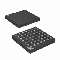
ATXMEGA16A4-CUR Atmel, ATXMEGA16A4-CUR Datasheet - Page 104

ATXMEGA16A4-CUR
Manufacturer Part Number
ATXMEGA16A4-CUR
Description
MCU AVR 16+4KB FLASH 49VFBGA
Manufacturer
Atmel
Series
AVR® XMEGAr
Specifications of ATXMEGA16A4-CUR
Core Processor
AVR
Core Size
8/16-Bit
Speed
32MHz
Connectivity
I²C, IrDA, SPI, UART/USART
Peripherals
Brown-out Detect/Reset, DMA, POR, PWM, WDT
Number Of I /o
34
Program Memory Size
16KB (8K x 16)
Program Memory Type
FLASH
Eeprom Size
1K x 8
Ram Size
2K x 8
Voltage - Supply (vcc/vdd)
1.6 V ~ 3.6 V
Data Converters
A/D 12x12b, D/A 2x12b
Oscillator Type
Internal
Operating Temperature
-40°C ~ 85°C
Package / Case
49-VFBGA
For Use With
ATAVRONEKIT - KIT AVR/AVR32 DEBUGGER/PROGRMMRATSTK600 - DEV KIT FOR AVR/AVR32770-1007 - ISP 4PORT ATMEL AVR MCU SPI/JTAG770-1004 - ISP 4PORT FOR ATMEL AVR MCU SPI
Lead Free Status / RoHS Status
Lead free / RoHS Compliant
Available stocks
Company
Part Number
Manufacturer
Quantity
Price
- Current page: 104 of 445
- Download datasheet (6Mb)
9.3
9.3.1
9.3.2
9.3.3
9.4
9.4.1
8077H–AVR–12/09
Reset Sequence
Reset Sources
Reset Counter Delay
Oscillator Startup
Oscillator Calibration
Power-On Reset
Reset request from any reset source immediately reset the device, and keep it in reset as long
as the request is active. When all reset requests are released, the device will go through three
stages before the internal reset is released and the device starts running.
If one of the reset request occur during this, the reset sequence will start over again.
The Reset Counter Delay is the programmable period from all reset requests are released and
until the reset counter times out and releases reset. The Reset Counter Delay is timed from the
1 kHz output of the Ultra Low Power (ULP) Internal Oscillator, and the number of cycles before
the timeout is set by the STARTUPTIME fuse bits. The selectable delays are shown in
1.
Table 9-1.
After the Reset Counter Delay, the default clock is started. This is the 2 MHz internal RC oscilla-
tor, and this uses 6 clock cycles to startup and stabilize.
After the default oscillator has stabilized, oscillator calibration values are loaded from Non-Vola-
tile Memory into the Oscillator Calibration registers. Loading the calibration values takes 24
clock cycles on the internal 2 MHz oscillator. The 2 MHz, 32 MHz and 32 kHz internal RC oscil-
lators are calibrated. When this is done the device will enter active mode and program execution
will begin.
A Power-on detection circuit will give a Power-On Reset (POR) when supply voltage (V
applied to the device and the V
Power-on reset is released when the V
Power-on Threshold Voltage (V
When V
lower than the minimum operating voltage for the device, and is only used for power-off function-
SUT[1:0]
• Reset Counter Delay
• Oscillator startup
• Oscillator calibration
00
01
10
11
CC
is falling, the POR will issue a reset when the Vpot level is reached. The Vpot level is
Reset Counter Delay
POT
Number of 1 kHz ULP oscillator clock cycles
CC
) level.
slope is increasing in the Power-on Slope Range (V
CC
stops rising or when the V
Reserved
64
4
0
CC
level has reached the
XMEGA A
Table 9-
POSR
CC
104
) is
).
Related parts for ATXMEGA16A4-CUR
Image
Part Number
Description
Manufacturer
Datasheet
Request
R

Part Number:
Description:
DEV KIT FOR AVR/AVR32
Manufacturer:
Atmel
Datasheet:

Part Number:
Description:
INTERVAL AND WIPE/WASH WIPER CONTROL IC WITH DELAY
Manufacturer:
ATMEL Corporation
Datasheet:

Part Number:
Description:
Low-Voltage Voice-Switched IC for Hands-Free Operation
Manufacturer:
ATMEL Corporation
Datasheet:

Part Number:
Description:
MONOLITHIC INTEGRATED FEATUREPHONE CIRCUIT
Manufacturer:
ATMEL Corporation
Datasheet:

Part Number:
Description:
AM-FM Receiver IC U4255BM-M
Manufacturer:
ATMEL Corporation
Datasheet:

Part Number:
Description:
Monolithic Integrated Feature Phone Circuit
Manufacturer:
ATMEL Corporation
Datasheet:

Part Number:
Description:
Multistandard Video-IF and Quasi Parallel Sound Processing
Manufacturer:
ATMEL Corporation
Datasheet:

Part Number:
Description:
High-performance EE PLD
Manufacturer:
ATMEL Corporation
Datasheet:

Part Number:
Description:
8-bit Flash Microcontroller
Manufacturer:
ATMEL Corporation
Datasheet:

Part Number:
Description:
2-Wire Serial EEPROM
Manufacturer:
ATMEL Corporation
Datasheet:


