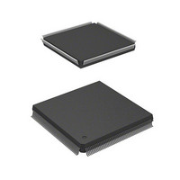
HD6417750RF200DV Renesas Electronics America, HD6417750RF200DV Datasheet - Page 962

HD6417750RF200DV
Manufacturer Part Number
HD6417750RF200DV
Description
MPU 1.5/3.3V 0K I-TEMP PB-FREE 2
Manufacturer
Renesas Electronics America
Series
SuperH® SH7750r
Datasheet
1.D6417750RBP240DV.pdf
(1164 pages)
Specifications of HD6417750RF200DV
Core Processor
SH-4
Core Size
32-Bit
Speed
200MHz
Connectivity
EBI/EMI, FIFO, SCI, SmartCard
Peripherals
DMA, POR, WDT
Number Of I /o
28
Program Memory Type
ROMless
Ram Size
48K x 8
Voltage - Supply (vcc/vdd)
1.35 V ~ 1.6 V
Oscillator Type
External
Operating Temperature
-40°C ~ 85°C
Package / Case
208-QFP Exposed Pad, 208-eQFP, 208-HQFP
Lead Free Status / RoHS Status
Lead free / RoHS Compliant
Eeprom Size
-
Program Memory Size
-
Data Converters
-
Available stocks
Company
Part Number
Manufacturer
Quantity
Price
Company:
Part Number:
HD6417750RF200DV
Manufacturer:
FREESCALE
Quantity:
450
- Current page: 962 of 1164
- Download datasheet (7Mb)
Section 20 User Break Controller (UBC)
20.6
In the SH7750S, this function stops the clock supplied to the user break controller and is used to
minimize power dissipation when the chip is operating. Note that, if you use this function, you
cannot use the user break controller. This function is not provided in the SH7750.
20.6.1
Setting the MSTP5 bit of the STBCR2 (inside the CPG) to 1 stops the clock supply and causes the
user break controller to enter the stopped state. Follow steps (1) to (5) below to set the MSTP5 bit
to 1 and enter the stopped state.
(1) Initialize BBRA and BBRB to 0;
(2) Initialize BRCR to 0;
(3) Make a dummy read of BRCR;
(4) Read STBCR2, then set the MSTP5 bit in the read data to 1 and write back.
(5) Make two dummy reads of STBCR2.
Make sure that, if an exception or interrupt occurs while performing steps (1) to (5), you do not
change the values of these registers in the exception handling routine.
Do not read or write the following registers while the user break controller clock is stopped:
BARA, BAMRA, BBRA, BARB, BAMRB, BBRB, BDRB, BDMRB, and BRCR. If these
registers are read or written, the value cannot be guaranteed.
20.6.2
The clock supply can be restarted by setting the MSTP5 bit of STBCR2 (inside the CPG) to 0. The
user break controller can then be operated again. Follow steps (6) and (7) below to clear the
MSTP5 bit to 0 to cancel the stopped state.
(6) Read STBCR2, then clear the MSTP5 bit in the read data to 0 and write the modified data
(7) Make two dummy reads of STBCR2.
As with the transition to the stopped state, if an exception or interrupt occurs while processing
steps (6) and (7), make sure that the values in these registers are not changed in the exception
handling routine.
Rev.7.00 Oct. 10, 2008 Page 876 of 1074
REJ09B0366-0700
back;
User Break Controller Stop Function
Transition to User Break Controller Stopped State
Cancelling the User Break Controller Stopped State
Related parts for HD6417750RF200DV
Image
Part Number
Description
Manufacturer
Datasheet
Request
R

Part Number:
Description:
KIT STARTER FOR M16C/29
Manufacturer:
Renesas Electronics America
Datasheet:

Part Number:
Description:
KIT STARTER FOR R8C/2D
Manufacturer:
Renesas Electronics America
Datasheet:

Part Number:
Description:
R0K33062P STARTER KIT
Manufacturer:
Renesas Electronics America
Datasheet:

Part Number:
Description:
KIT STARTER FOR R8C/23 E8A
Manufacturer:
Renesas Electronics America
Datasheet:

Part Number:
Description:
KIT STARTER FOR R8C/25
Manufacturer:
Renesas Electronics America
Datasheet:

Part Number:
Description:
KIT STARTER H8S2456 SHARPE DSPLY
Manufacturer:
Renesas Electronics America
Datasheet:

Part Number:
Description:
KIT STARTER FOR R8C38C
Manufacturer:
Renesas Electronics America
Datasheet:

Part Number:
Description:
KIT STARTER FOR R8C35C
Manufacturer:
Renesas Electronics America
Datasheet:

Part Number:
Description:
KIT STARTER FOR R8CL3AC+LCD APPS
Manufacturer:
Renesas Electronics America
Datasheet:

Part Number:
Description:
KIT STARTER FOR RX610
Manufacturer:
Renesas Electronics America
Datasheet:

Part Number:
Description:
KIT STARTER FOR R32C/118
Manufacturer:
Renesas Electronics America
Datasheet:

Part Number:
Description:
KIT DEV RSK-R8C/26-29
Manufacturer:
Renesas Electronics America
Datasheet:

Part Number:
Description:
KIT STARTER FOR SH7124
Manufacturer:
Renesas Electronics America
Datasheet:

Part Number:
Description:
KIT STARTER FOR H8SX/1622
Manufacturer:
Renesas Electronics America
Datasheet:

Part Number:
Description:
KIT DEV FOR SH7203
Manufacturer:
Renesas Electronics America
Datasheet:


