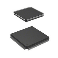
HD6417750RF200DV Renesas Electronics America, HD6417750RF200DV Datasheet - Page 823

HD6417750RF200DV
Manufacturer Part Number
HD6417750RF200DV
Description
MPU 1.5/3.3V 0K I-TEMP PB-FREE 2
Manufacturer
Renesas Electronics America
Series
SuperH® SH7750r
Datasheet
1.D6417750RBP240DV.pdf
(1164 pages)
Specifications of HD6417750RF200DV
Core Processor
SH-4
Core Size
32-Bit
Speed
200MHz
Connectivity
EBI/EMI, FIFO, SCI, SmartCard
Peripherals
DMA, POR, WDT
Number Of I /o
28
Program Memory Type
ROMless
Ram Size
48K x 8
Voltage - Supply (vcc/vdd)
1.35 V ~ 1.6 V
Oscillator Type
External
Operating Temperature
-40°C ~ 85°C
Package / Case
208-QFP Exposed Pad, 208-eQFP, 208-HQFP
Lead Free Status / RoHS Status
Lead free / RoHS Compliant
Eeprom Size
-
Program Memory Size
-
Data Converters
-
Available stocks
Company
Part Number
Manufacturer
Quantity
Price
Company:
Part Number:
HD6417750RF200DV
Manufacturer:
FREESCALE
Quantity:
450
- Current page: 823 of 1164
- Download datasheet (7Mb)
16.2.7
Note:
SCFSR2 is a 16-bit register. The lower 8 bits consist of status flags that indicate the operating
status of the SCIF, and the upper 8 bits indicate the number of receive errors in the data in the
receive FIFO register.
SCFSR2 can be read or written to by the CPU at all times. However, 1 cannot be written to flags
ER, TEND, TDFE, BRK, RDF, and DR. Also note that in order to clear these flags they must be
read as 1 beforehand. The FER flag and PER flag are read-only flags and cannot be modified.
SCFSR2 is initialized to H'0060 by a power-on reset or manual reset. It is not initialized in
standby mode or in the module standby state.
Bits 15 to 12—Number of Parity Errors (PER3–PER0): These bits indicate the number of data
bytes in which a parity error occurred in the receive data stored in SCFRDR2.
After the ER bit in SCFSR2 is set, the value indicated by bits 15 to 12 is the number of data bytes
in which a parity error occurred.
If all 16 bytes of receive data in SCFRDR2 have parity errors, the value indicated by bits PER3 to
PER0 will be 0.
Bits 11 to 8—Number of Framing Errors (FER3–FER0): These bits indicate the number of
data bytes in which a framing error occurred in the receive data stored in SCFRDR2.
After the ER bit in SCFSR2 is set, the value indicated by bits 11 to 8 is the number of data bytes in
which a framing error occurred.
Initial value:
Initial value:
*
Serial Status Register (SCFSR2)
Only 0 can be written, to clear the flag.
R/W:
R/W:
Bit:
Bit:
R/(W)*
PER3
ER
15
R
0
7
0
R/(W)*
TEND
PER2
14
R
0
6
1
Section 16 Serial Communication Interface with FIFO (SCIF)
R/(W)*
PER1
TDFE
13
R
0
5
1
R/(W)*
PER0
BRK
12
R
0
4
0
Rev.7.00 Oct. 10, 2008 Page 737 of 1074
FER3
FER
11
R
R
0
3
0
FER2
PER
10
R
R
0
2
0
REJ09B0366-0700
R/(W)*
FER1
RDF
R
9
0
1
0
R/(W)*
FER0
DR
R
8
0
0
0
Related parts for HD6417750RF200DV
Image
Part Number
Description
Manufacturer
Datasheet
Request
R

Part Number:
Description:
KIT STARTER FOR M16C/29
Manufacturer:
Renesas Electronics America
Datasheet:

Part Number:
Description:
KIT STARTER FOR R8C/2D
Manufacturer:
Renesas Electronics America
Datasheet:

Part Number:
Description:
R0K33062P STARTER KIT
Manufacturer:
Renesas Electronics America
Datasheet:

Part Number:
Description:
KIT STARTER FOR R8C/23 E8A
Manufacturer:
Renesas Electronics America
Datasheet:

Part Number:
Description:
KIT STARTER FOR R8C/25
Manufacturer:
Renesas Electronics America
Datasheet:

Part Number:
Description:
KIT STARTER H8S2456 SHARPE DSPLY
Manufacturer:
Renesas Electronics America
Datasheet:

Part Number:
Description:
KIT STARTER FOR R8C38C
Manufacturer:
Renesas Electronics America
Datasheet:

Part Number:
Description:
KIT STARTER FOR R8C35C
Manufacturer:
Renesas Electronics America
Datasheet:

Part Number:
Description:
KIT STARTER FOR R8CL3AC+LCD APPS
Manufacturer:
Renesas Electronics America
Datasheet:

Part Number:
Description:
KIT STARTER FOR RX610
Manufacturer:
Renesas Electronics America
Datasheet:

Part Number:
Description:
KIT STARTER FOR R32C/118
Manufacturer:
Renesas Electronics America
Datasheet:

Part Number:
Description:
KIT DEV RSK-R8C/26-29
Manufacturer:
Renesas Electronics America
Datasheet:

Part Number:
Description:
KIT STARTER FOR SH7124
Manufacturer:
Renesas Electronics America
Datasheet:

Part Number:
Description:
KIT STARTER FOR H8SX/1622
Manufacturer:
Renesas Electronics America
Datasheet:

Part Number:
Description:
KIT DEV FOR SH7203
Manufacturer:
Renesas Electronics America
Datasheet:


