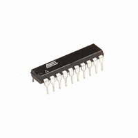
ATTINY2313A-PU Atmel, ATTINY2313A-PU Datasheet - Page 68

ATTINY2313A-PU
Manufacturer Part Number
ATTINY2313A-PU
Description
IC MCU AVR 2K FLASH 20MHZ 20DIP
Manufacturer
Atmel
Series
AVR® ATtinyr
Specifications of ATTINY2313A-PU
Core Processor
AVR
Core Size
8-Bit
Speed
20MHz
Connectivity
I²C, SPI, UART/USART
Peripherals
Brown-out Detect/Reset, POR, PWM, WDT
Number Of I /o
18
Program Memory Size
2KB (1K x 16)
Program Memory Type
FLASH
Eeprom Size
128 x 8
Ram Size
128 x 8
Voltage - Supply (vcc/vdd)
1.8 V ~ 5.5 V
Oscillator Type
Internal
Operating Temperature
-40°C ~ 85°C
Package / Case
20-DIP (0.300", 7.62mm)
Processor Series
ATTINY2x
Core
AVR8
Data Bus Width
8 bit
Data Ram Size
128 B
Interface Type
SPI, USART
Maximum Clock Frequency
20 MHz
Number Of Programmable I/os
18
Operating Supply Voltage
1.8 V to 5.5 V
Maximum Operating Temperature
+ 85 C
Mounting Style
Through Hole
3rd Party Development Tools
EWAVR, EWAVR-BL
Development Tools By Supplier
ATAVRDRAGON, ATSTK500, ATSTK600, ATAVRISP2, ATAVRONEKIT
Minimum Operating Temperature
- 40 C
Controller Family/series
ATtiny
No. Of I/o's
18
Eeprom Memory Size
128Byte
Ram Memory Size
128Byte
Cpu Speed
20MHz
Rohs Compliant
Yes
Lead Free Status / RoHS Status
Lead free / RoHS Compliant
Data Converters
-
Lead Free Status / Rohs Status
Lead free / RoHS Compliant
Available stocks
Company
Part Number
Manufacturer
Quantity
Price
Company:
Part Number:
ATTINY2313A-PU
Manufacturer:
TI
Quantity:
1 560
Part Number:
ATTINY2313A-PU
Manufacturer:
ATMEL/爱特梅尔
Quantity:
20 000
- Current page: 68 of 270
- Download datasheet (7Mb)
10.3
10.3.1
10.3.2
10.3.3
68
Register Description
ATtiny2313A/4313
MCUCR – MCU Control Register
PORTA – Port A Data Register
DDRA – Port A Data Direction Register
Table 10-10. Overriding Signals for Alternate Functions in PD3..PD0
• Bit 7 – PUD: Pull-up Disable
When this bit is written to one, the pull-ups in the I/O ports are disabled even if the DDxn and
PORTxn Registers are configured to enable the pull-ups ({DDxn, PORTxn} = 0b01). See
figuring the Pin” on page 55
Bit
0x35 (0x55)
Read/Write
Initial Value
Bit
0x1B (0x3B)
Read/Write
Initial Value
Bit
0x1A (0x3A)
Read/Write
Initial Value
Signal
Name
PUOE
PUOV
DDOE
DDOV
PVOE
PVOV
PTOE
DIEOE
DIEOV
DI
AIO
PD3/INT1/
PCINT14
0
0
0
0
0
0
0
INT1 Enable +
PCINT14
PCINT14
INT1 Input/
PCINT14
–
PUD
R/W
R
R
7
–
0
7
–
0
0
7
SM1
R/W
R
R
6
–
0
6
–
0
6
0
PD2/INT0/XCK/CKOUT/
PCINT13
0
0
0
0
XCKO_PVOE
XCKO_PVOV
0
INT0 Enable/
XCK Input Enable/PCINT13
PCINT13
INT0 Input/XCK Input/
PCINT13
–
for more details about this feature.
R
R
5
0
5
0
–
–
R/W
SE
5
0
R
R
4
–
0
4
–
0
SM0
R/W
4
0
R
R
3
–
0
3
–
0
ISC11
R/W
3
0
PORTA2
PD1/TXD/
PCINT12
TXD_OE
0
TXD_OE
1
TXD_OE
TXD_PVOV
0
PCINT12
PCINT12
PCINT12
–
DDA2
R/W
R/W
2
0
2
0
ISC10
R/W
2
0
PORTA1
DDA1
R/W
R/W
ISC01
1
0
1
0
R/W
1
0
PD0/RXD/PCINT11
RXD_OE
PORTD0 • PUD
RXD_EN
0
0
0
0
PCINT11
PCINT11
RXD Input/PCINT11
–
PORTA0
DDA0
R/W
R/W
ISC00
R/W
0
0
0
0
0
0
8246A–AVR–11/09
PORTA
MCUCR
DDRA
“Con-
Related parts for ATTINY2313A-PU
Image
Part Number
Description
Manufacturer
Datasheet
Request
R

Part Number:
Description:
IC, MCU, 8BIT, 2K FLASH, 20SOIC
Manufacturer:
Atmel
Datasheet:

Part Number:
Description:
IC, MCU, 8BIT, 2K FLASH, 20PDIP
Manufacturer:
Atmel
Datasheet:

Part Number:
Description:
IC, MCU, 8BIT, 8K FLASH, 20PDIP
Manufacturer:
Atmel
Datasheet:

Part Number:
Description:
IC, MCU, 8BIT, 8K FLASH, 20SOIC
Manufacturer:
Atmel
Datasheet:

Part Number:
Description:
DEV KIT FOR AVR/AVR32
Manufacturer:
Atmel
Datasheet:

Part Number:
Description:
INTERVAL AND WIPE/WASH WIPER CONTROL IC WITH DELAY
Manufacturer:
ATMEL Corporation
Datasheet:

Part Number:
Description:
Low-Voltage Voice-Switched IC for Hands-Free Operation
Manufacturer:
ATMEL Corporation
Datasheet:

Part Number:
Description:
MONOLITHIC INTEGRATED FEATUREPHONE CIRCUIT
Manufacturer:
ATMEL Corporation
Datasheet:

Part Number:
Description:
AM-FM Receiver IC U4255BM-M
Manufacturer:
ATMEL Corporation
Datasheet:

Part Number:
Description:
Monolithic Integrated Feature Phone Circuit
Manufacturer:
ATMEL Corporation
Datasheet:

Part Number:
Description:
Multistandard Video-IF and Quasi Parallel Sound Processing
Manufacturer:
ATMEL Corporation
Datasheet:

Part Number:
Description:
High-performance EE PLD
Manufacturer:
ATMEL Corporation
Datasheet:


