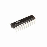
ATTINY2313A-PU Atmel, ATTINY2313A-PU Datasheet - Page 267

ATTINY2313A-PU
Manufacturer Part Number
ATTINY2313A-PU
Description
IC MCU AVR 2K FLASH 20MHZ 20DIP
Manufacturer
Atmel
Series
AVR® ATtinyr
Specifications of ATTINY2313A-PU
Core Processor
AVR
Core Size
8-Bit
Speed
20MHz
Connectivity
I²C, SPI, UART/USART
Peripherals
Brown-out Detect/Reset, POR, PWM, WDT
Number Of I /o
18
Program Memory Size
2KB (1K x 16)
Program Memory Type
FLASH
Eeprom Size
128 x 8
Ram Size
128 x 8
Voltage - Supply (vcc/vdd)
1.8 V ~ 5.5 V
Oscillator Type
Internal
Operating Temperature
-40°C ~ 85°C
Package / Case
20-DIP (0.300", 7.62mm)
Processor Series
ATTINY2x
Core
AVR8
Data Bus Width
8 bit
Data Ram Size
128 B
Interface Type
SPI, USART
Maximum Clock Frequency
20 MHz
Number Of Programmable I/os
18
Operating Supply Voltage
1.8 V to 5.5 V
Maximum Operating Temperature
+ 85 C
Mounting Style
Through Hole
3rd Party Development Tools
EWAVR, EWAVR-BL
Development Tools By Supplier
ATAVRDRAGON, ATSTK500, ATSTK600, ATAVRISP2, ATAVRONEKIT
Minimum Operating Temperature
- 40 C
Controller Family/series
ATtiny
No. Of I/o's
18
Eeprom Memory Size
128Byte
Ram Memory Size
128Byte
Cpu Speed
20MHz
Rohs Compliant
Yes
Lead Free Status / RoHS Status
Lead free / RoHS Compliant
Data Converters
-
Lead Free Status / Rohs Status
Lead free / RoHS Compliant
Available stocks
Company
Part Number
Manufacturer
Quantity
Price
Company:
Part Number:
ATTINY2313A-PU
Manufacturer:
TI
Quantity:
1 560
Part Number:
ATTINY2313A-PU
Manufacturer:
ATMEL/爱特梅尔
Quantity:
20 000
8246A–AVR–11/09
13 Timer/Counter0 and Timer/Counter1 Prescalers .............................. 117
14 USART ................................................................................................... 119
15 USART in SPI Mode ............................................................................. 145
16 USI – Universal Serial Interface .......................................................... 155
12.5
12.6
12.7
12.8
12.9
12.10
12.11
13.1
13.2
13.3
13.4
14.1
14.2
14.3
14.4
14.5
14.6
14.7
14.8
14.9
14.10
14.11
15.1
15.2
15.3
15.4
15.5
15.6
15.7
15.8
16.1
Input Capture Unit ...........................................................................................91
Output Compare Units .....................................................................................93
Compare Match Output Unit ............................................................................95
Modes of Operation .........................................................................................96
Timer/Counter Timing Diagrams ...................................................................104
Accessing 16-bit Registers ............................................................................106
Register Description ......................................................................................110
Internal Clock Source ....................................................................................117
Prescaler Reset .............................................................................................117
External Clock Source ...................................................................................117
Register Description ......................................................................................118
Features ........................................................................................................119
Overview ........................................................................................................119
Clock Generation ...........................................................................................120
Frame Formats ..............................................................................................123
USART Initialization .......................................................................................124
Data Transmission – The USART Transmitter ..............................................125
Data Reception – The USART Receiver .......................................................129
Asynchronous Data Reception ......................................................................132
Multi-processor Communication Mode ..........................................................135
Register Description ......................................................................................136
Examples of Baud Rate Setting .....................................................................141
Features ........................................................................................................145
Overview ........................................................................................................145
Clock Generation ...........................................................................................145
SPI Data Modes and Timing ..........................................................................146
Frame Formats ..............................................................................................147
Data Transfer .................................................................................................149
AVR USART MSPIM vs. AVR SPI ................................................................151
Register Description ......................................................................................152
Features ........................................................................................................155
iii


