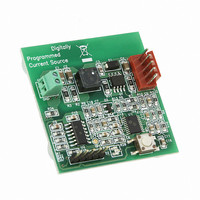
MCP1631RD-DCPC1 Microchip Technology, MCP1631RD-DCPC1 Datasheet - Page 122

MCP1631RD-DCPC1
Manufacturer Part Number
MCP1631RD-DCPC1
Description
REF DES BATT CHARG OR LED DRIVER
Manufacturer
Microchip Technology
Datasheets
1.PIC16F616T-ISL.pdf
(214 pages)
2.MCP1631VHVT-330EST.pdf
(34 pages)
3.MCP1631VHVT-330EST.pdf
(32 pages)
Specifications of MCP1631RD-DCPC1
Current - Output / Channel
700mA
Outputs And Type
1, Non-Isolated
Features
Firmware for Li-Ion, NiMH, and NiCd Battery Charger
Voltage - Input
3.5 ~ 16 V
Utilized Ic / Part
MCP1631HV, PIC16F616
Core Chip
MCP1631HV, PIC16F616
Topology
Parallel, Series
Output Current
1A
No. Of Outputs
1
Input Voltage
3.5V To 16V
Dimming Control Type
Analog
Kit Contents
Board
Lead Free Status / RoHS Status
Lead free / RoHS Compliant
Voltage - Output
-
Lead Free Status / Rohs Status
Lead free / RoHS Compliant
- PIC16F616T-ISL PDF datasheet
- MCP1631VHVT-330EST PDF datasheet #2
- MCP1631VHVT-330EST PDF datasheet #3
- Current page: 122 of 214
- Download datasheet (4Mb)
PIC16F610/616/16HV610/616
12.6
The Watchdog Timer is a free running, on-chip RC
oscillator, which requires no external components. This
RC oscillator is separate from the external RC oscillator
of the CLKIN pin and INTOSC. That means that the
WDT will run, even if the clock on the OSC1 and OSC2
pins of the device has been stopped (for example, by
execution of a SLEEP instruction). During normal oper-
ation, a WDT Time-out generates a device Reset. If the
device is in Sleep mode, a WDT Time-out causes the
device to wake-up and continue with normal operation.
The WDT can be permanently disabled by program-
ming
(Section 12.1 “Configuration Bits”).
FIGURE 12-2:
TABLE 12-7:
DS41288F-page 122
WDTE = 0
CLRWDT Command
Exit Sleep + System Clock = EXTRC, INTRC, EC
Exit Sleep + System Clock = XT, HS, LP
T0CKI
pin
(= F
CLKOUT
the
Note 1: T0SE, T0CS, PSA, PS<2:0> are bits in the OPTION register.
OSC
T0SE
Watchdog Timer (WDT)
/4)
Configuration
WDT STATUS
Watchdog
WDTE
Timer
WATCHDOG TIMER BLOCK DIAGRAM
T0CS
0
1
bit,
WDTE,
Conditions
PSA
0
1
as
Prescaler
clear
8-bit
8
PS<2:0>
12.6.1
The WDT has a nominal time-out period of 18 ms (with
no prescaler). The time-out periods vary with
temperature, V
part (see Table 15-4, Parameter 31). If longer time-out
periods are desired, a prescaler with a division ratio of
up to 1:128 can be assigned to the WDT under
software control by writing to the OPTION register.
Thus, time-out periods up to 2.3 seconds can be
realized.
The CLRWDT and SLEEP instructions clear the WDT
and the prescaler, if assigned to the WDT, and prevent
it from timing out and generating a device Reset.
The TO bit in the STATUS register will be cleared upon
a Watchdog Timer Time-out.
12.6.2
It should also be taken in account that under worst-
case conditions (i.e., V
Max. WDT prescaler) it may take several seconds
before a WDT Time-out occurs.
3
WDT PERIOD
WDT PROGRAMMING
CONSIDERATIONS
PSA
PSA
1
0
1
0
DD
and process variations from part to
SYNC 2
Time-Out
Cycles
DD
WDT
Cleared until the end of OST
© 2009 Microchip Technology Inc.
= Min., Temperature = Max.,
Cleared
WDT
Data Bus
Set Flag bit T0IF
8
TMR0
on Overflow
Related parts for MCP1631RD-DCPC1
Image
Part Number
Description
Manufacturer
Datasheet
Request
R

Part Number:
Description:
REFERENCE DESIGN MCP1631HV
Manufacturer:
Microchip Technology
Datasheet:

Part Number:
Description:
REFERENCE DESIGN FOR MCP1631HV
Manufacturer:
Microchip Technology
Datasheet:

Part Number:
Description:
Manufacturer:
Microchip Technology Inc.
Datasheet:

Part Number:
Description:
Manufacturer:
Microchip Technology Inc.
Datasheet:

Part Number:
Description:
Manufacturer:
Microchip Technology Inc.
Datasheet:

Part Number:
Description:
Manufacturer:
Microchip Technology Inc.
Datasheet:

Part Number:
Description:
Manufacturer:
Microchip Technology Inc.
Datasheet:

Part Number:
Description:
Manufacturer:
Microchip Technology Inc.
Datasheet:

Part Number:
Description:
Manufacturer:
Microchip Technology Inc.
Datasheet:

Part Number:
Description:
Manufacturer:
Microchip Technology Inc.
Datasheet:


