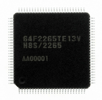
DF2265TE13V Renesas Electronics America, DF2265TE13V Datasheet - Page 19

DF2265TE13V
Manufacturer Part Number
DF2265TE13V
Description
IC H8S/2265 MCU FLASH 100TQFP
Manufacturer
Renesas Electronics America
Series
H8® H8S/2200r
Specifications of DF2265TE13V
Core Processor
H8S/2000
Core Size
16-Bit
Speed
13MHz
Connectivity
I²C, SCI, SmartCard
Peripherals
LCD, POR, PWM, WDT
Number Of I /o
67
Program Memory Size
128KB (128K x 8)
Program Memory Type
FLASH
Ram Size
4K x 8
Voltage - Supply (vcc/vdd)
3 V ~ 5.5 V
Data Converters
A/D 10x10b, D/A 2x8b
Oscillator Type
Internal
Operating Temperature
-20°C ~ 75°C
Package / Case
100-TQFP, 100-VQFP
Lead Free Status / RoHS Status
Lead free / RoHS Compliant
Eeprom Size
-
Available stocks
Company
Part Number
Manufacturer
Quantity
Price
Company:
Part Number:
DF2265TE13V
Manufacturer:
Renesas Electronics America
Quantity:
10 000
- Current page: 19 of 712
- Download datasheet (5Mb)
Item
14.4.6 Slave
Transmit Operation
15.2 Input/Output Pins
Table 15.1 Pin
Configuration
15.8.4 Range of
Analog Power Supply
and Other Pin
Settings
20.6.1 Boot Mode
Table 20.4 Boot
Mode Operation
25.2.2 DC
Characteristics
Table 25.2 DC
Characteristics (1)
Page
424
445
460
520
600
Revision (See Manual for Details)
Description added
10. When the stop condition is detected, that is, when SDA is
Table amended
Note added
Note: * AN0 and AN1 can be used only when Vcc = AVcc.
Description added
•
Table replaced
Table amended
Note added
Notes: 4. When Vcc < AVcc, the maximum value for P40 and
Pin Name
Analog input pin 0
Analog input pin 1
Analog input pin 2
Analog input pin 3
Item
Input high
voltage
Relationship between AVcc, AVss and Vcc, Vss.
Set AVss = Vss as the relationship between AVcc, AVss and
Vcc, Vss. If the A/D converter is not used, the AVcc and
AVss pins must not be left open. In addition, analog input
pins AN0 and AN1 can be used only when Vcc = AVcc.
changed from low to high when SCL is high, the BBSY flag
in ICCR is cleared to 0 and the STOP flag in ICSR is set to
1. At the same time, the IRIC flag is set to 1. If the IRIC flag
has been set, it is cleared to 0.
To restart slave transmit mode operation, make the initial
settings once again.
RES, STBY, NMI,
FWE, MD2, MD1
EXTAL, Ports 1, 3,
7, F, J to N,
PH0 to PH3
Ports 4 *
P41 is Vcc + 0.3 V.
4
, 9, PH7
Symbol
AN0*
AN1*
AN2
AN3
Symbol
V
IH
Rev. 5.00 Sep. 01, 2009 Page xvii of l
I/O
Input
Input
Input
Input
Min.
V
V
V
CC
CC
CC
× 0.9
× 0.8
×
0.8
Function
Group 0 analog input pins
Typ.
Max.
V
V
AV
CC
CC
CC
+ 0.3
+ 0.3
+ 0.3 *
REJ09B0071-0500
4
Unit
V
V
V
Test Conditions
Related parts for DF2265TE13V
Image
Part Number
Description
Manufacturer
Datasheet
Request
R

Part Number:
Description:
CONN SOCKET 2POS 7.92MM WHITE
Manufacturer:
Hirose Electric Co Ltd
Datasheet:

Part Number:
Description:
CONN SOCKET 4POS 7.92MM WHITE
Manufacturer:
Hirose Electric Co Ltd
Datasheet:

Part Number:
Description:
CONN SOCKET 5POS 7.92MM WHITE
Manufacturer:
Hirose Electric Co Ltd
Datasheet:

Part Number:
Description:
CONN SOCKET 3POS 7.92MM WHITE
Manufacturer:
Hirose Electric Co Ltd
Datasheet:

Part Number:
Description:
CONN SOCKET 5POS 7.92MM WHITE
Manufacturer:
Hirose Electric Co Ltd
Datasheet:

Part Number:
Description:
CONN SOCKET 2POS 7.92MM WHITE
Manufacturer:
Hirose Electric Co Ltd
Datasheet:

Part Number:
Description:
CONN SOCKET 3POS 7.92MM WHITE
Manufacturer:
Hirose Electric Co Ltd
Datasheet:

Part Number:
Description:
CONN SOCKET 4POS 7.92MM WHITE
Manufacturer:
Hirose Electric Co Ltd
Datasheet:

Part Number:
Description:
CONN HEADER 2POS 7.92MM R/A TIN
Manufacturer:
Hirose Electric Co Ltd
Datasheet:

Part Number:
Description:
CONN HEADER 4POS 7.92MM R/A TIN
Manufacturer:
Hirose Electric Co Ltd
Datasheet:

Part Number:
Description:
KIT STARTER FOR M16C/29
Manufacturer:
Renesas Electronics America
Datasheet:

Part Number:
Description:
KIT STARTER FOR R8C/2D
Manufacturer:
Renesas Electronics America
Datasheet:

Part Number:
Description:
R0K33062P STARTER KIT
Manufacturer:
Renesas Electronics America
Datasheet:

Part Number:
Description:
KIT STARTER FOR R8C/23 E8A
Manufacturer:
Renesas Electronics America
Datasheet:

Part Number:
Description:
KIT STARTER FOR R8C/25
Manufacturer:
Renesas Electronics America
Datasheet:


