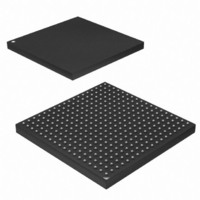
AT91SAM9G45-CU-999 Atmel, AT91SAM9G45-CU-999 Datasheet - Page 952

AT91SAM9G45-CU-999
Manufacturer Part Number
AT91SAM9G45-CU-999
Description
IC MCU ARM9 APMC 324TFBGA
Manufacturer
Atmel
Series
AT91SAMr
Datasheet
1.AT91SAM9G45-EKES.pdf
(1218 pages)
Specifications of AT91SAM9G45-CU-999
Core Processor
ARM9
Core Size
16/32-Bit
Speed
400MHz
Connectivity
EBI/EMI, Ethernet, I²C, IrDA, MMC, SPI, SSC, UART/USART, USB
Peripherals
AC'97, DMA, I²S, LCD, POR, PWM, WDT
Number Of I /o
160
Program Memory Size
64KB (64K x 8)
Program Memory Type
ROM
Ram Size
128K x 8
Voltage - Supply (vcc/vdd)
0.9 V ~ 1.1 V
Data Converters
A/D 8x10b
Oscillator Type
Internal
Operating Temperature
-40°C ~ 85°C
Package / Case
324-TFBGA
Lead Free Status / RoHS Status
Lead free / RoHS Compliant
Eeprom Size
-
Lead Free Status / Rohs Status
Supplier Unconfirmed
Available stocks
Company
Part Number
Manufacturer
Quantity
Price
- Current page: 952 of 1218
- Download datasheet (19Mb)
40.10.4
6438F–ATARM–21-Jun-10
Manual Mode
The Trigger Counter is cleared when TSAMOD is written to define the Interleaved Mode, then it
simply rolls over.
The TSADCC features a manual mode allowing to control the state (open/close) of the four
switches.
Writing TSAMOD to “Manual Mode” automatically enables the ADC pins as analog inputs.The
switches positions are controlled through the
this mode, the “Sample and Hold Time” used is the one defined for the Touchscreen mode
(TSSHTIM).
To perform a measurement, the following sequence must be followed
• For Trigger Counter at 5:
1. Close the switches on the inputs Y
2. Convert Channel Y
3. If Channel 4 to Channel 7 are enabled, convert Channels and store result in the corre-
4. Set Trigger Counter to 6.
• For Trigger Counter at 6:
1. Close the switches on the inputs Y
2. Convert Channel Y
3. If Channel 4 to Channel 7 are enabled, convert Channels and store result in the corre-
4. Set Trigger Counter to 7.
• For Trigger Counter at 7:
1. Close the switches on the inputs Y
2. Convert Channel X
3. If Channel 4 to Channel 7 are enabled, convert Channels and store result in the corre-
4. Set Trigger Counter to 8.
• For Trigger Counter between 8 and (2
1. Increment Trigger Counter.
2. If Trigger Counter equals (2
3. If Channel 4 to Channel 7 are enabled, convert Channels and store result in the corre-
1. Select the switch (switches) to close.
2. If SLEEP is set, wake up the ADC cell and wait for the Startup Time.
TSADCC_XPDR in TSADCC_LCDR if PDCEN is enabled).
sponding TSADCC_CDRx and TSADCC_LCDR.
result in TSADCC_CDR2 (and also in TSADCC_LCDR if PDCEN is enabled).
sponding TSADCC_CDRx and TSADCC_LCDR.
result in TSADCC_CDR3 (and also in TSADCC_LCDR if PDCEN is enabled).
sponding TSADCC_CDRx and TSADCC_LCDR.
sponding TSADCC_CDRx and TSADCC_LCDR.
P
P
M
, subtract TSADCC_CDR3 from the result and store the subtraction
, subtract TSADCC_CDR3 from the result and store the subtraction
and store the result in TSADCC_CDR3 (and store content of
TSFREQ+1
P
P
P
TSFREQ+1
), then set Trigger Counter to 0.
and Y
and Y
and Y
“TSADCC Manual Switch Command
M
M
M
):
during the Sample and Hold Time.
during the Sample and Hold Time.
during the Sample and Hold Time
AT91SAM9G45
Register”. In
952
Related parts for AT91SAM9G45-CU-999
Image
Part Number
Description
Manufacturer
Datasheet
Request
R

Part Number:
Description:
KIT EVAL FOR AT91SAM9G45
Manufacturer:
Atmel
Datasheet:

Part Number:
Description:
MCU ARM9 324-TFBGA
Manufacturer:
Atmel
Datasheet:

Part Number:
Description:
At91 Arm Thumb-based Microcontrollers
Manufacturer:
ATMEL Corporation
Datasheet:

Part Number:
Description:
MCU, MPU & DSP Development Tools KICKSTART KIT FOR AT91SAM9 PLUS
Manufacturer:
IAR Systems

Part Number:
Description:
DEV KIT FOR AVR/AVR32
Manufacturer:
Atmel
Datasheet:

Part Number:
Description:
INTERVAL AND WIPE/WASH WIPER CONTROL IC WITH DELAY
Manufacturer:
ATMEL Corporation
Datasheet:

Part Number:
Description:
Low-Voltage Voice-Switched IC for Hands-Free Operation
Manufacturer:
ATMEL Corporation
Datasheet:

Part Number:
Description:
MONOLITHIC INTEGRATED FEATUREPHONE CIRCUIT
Manufacturer:
ATMEL Corporation
Datasheet:

Part Number:
Description:
AM-FM Receiver IC U4255BM-M
Manufacturer:
ATMEL Corporation
Datasheet:

Part Number:
Description:
Monolithic Integrated Feature Phone Circuit
Manufacturer:
ATMEL Corporation
Datasheet:

Part Number:
Description:
Multistandard Video-IF and Quasi Parallel Sound Processing
Manufacturer:
ATMEL Corporation
Datasheet:

Part Number:
Description:
High-performance EE PLD
Manufacturer:
ATMEL Corporation
Datasheet:


