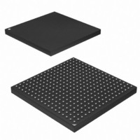
AT91SAM9G45-CU-999 Atmel, AT91SAM9G45-CU-999 Datasheet - Page 805

AT91SAM9G45-CU-999
Manufacturer Part Number
AT91SAM9G45-CU-999
Description
IC MCU ARM9 APMC 324TFBGA
Manufacturer
Atmel
Series
AT91SAMr
Datasheet
1.AT91SAM9G45-EKES.pdf
(1218 pages)
Specifications of AT91SAM9G45-CU-999
Core Processor
ARM9
Core Size
16/32-Bit
Speed
400MHz
Connectivity
EBI/EMI, Ethernet, I²C, IrDA, MMC, SPI, SSC, UART/USART, USB
Peripherals
AC'97, DMA, I²S, LCD, POR, PWM, WDT
Number Of I /o
160
Program Memory Size
64KB (64K x 8)
Program Memory Type
ROM
Ram Size
128K x 8
Voltage - Supply (vcc/vdd)
0.9 V ~ 1.1 V
Data Converters
A/D 8x10b
Oscillator Type
Internal
Operating Temperature
-40°C ~ 85°C
Package / Case
324-TFBGA
Lead Free Status / RoHS Status
Lead free / RoHS Compliant
Eeprom Size
-
Lead Free Status / Rohs Status
Supplier Unconfirmed
Available stocks
Company
Part Number
Manufacturer
Quantity
Price
- Current page: 805 of 1218
- Download datasheet (19Mb)
AT91SAM9G45
0 = The HSMCI is not ready for new data transfer. Cleared at the end of the card response.
1 = The HSMCI is ready for new data transfer. Set when the busy state on the data line has ended. This corresponds to a
free internal data receive buffer of the card.
Refer to the MMC or SD Specification for more details concerning the busy behavior.
For all the read operations, the NOTBUSY flag is cleared at the end of the host command.
For the Infinite Read Multiple Blocks, the NOTBUSY flag is set at the end of the STOP_TRANSMISSION host command
(CMD12).
For the Single Block Reads, the NOTBUSY flag is set at the end of the data read block.
For the Multiple Block Reads with pre-defined block count, the NOTBUSY flag is set at the end of the last received data
block.
• SDIOIRQA: SDIO Interrupt for Slot A
0 = No interrupt detected on SDIO Slot A.
1 = An SDIO Interrupt on Slot A occurred. Cleared when reading the HSMCI_SR.
• SDIOWAIT: SDIO Read Wait Operation Status
0 = Normal Bus operation.
1 = The data bus has entered IO wait state.
• CSRCV: CE-ATA Completion Signal Received
0 = No completion signal received since last status read operation.
1 = The device has issued a command completion signal on the command line. Cleared by reading in the HSMCI_SR
register.
• RINDE: Response Index Error
0 = No error.
1 = A mismatch is detected between the command index sent and the response index received. Cleared when writing in
the HSMCI_CMDR.
• RDIRE: Response Direction Error
0 = No error.
1 = The direction bit from card to host in the response has not been detected.
• RCRCE: Response CRC Error
0 = No error.
1 = A CRC7 error has been detected in the response. Cleared when writing in the HSMCI_CMDR.
• RENDE: Response End Bit Error
0 = No error.
1 = The end bit of the response has not been detected. Cleared when writing in the HSMCI_CMDR.
• RTOE: Response Time-out Error
0 = No error.
1 = The response time-out set by MAXLAT in the HSMCI_CMDR has been exceeded. Cleared when writing in the
HSMCI_CMDR.
805
6438F–ATARM–21-Jun-10
Related parts for AT91SAM9G45-CU-999
Image
Part Number
Description
Manufacturer
Datasheet
Request
R

Part Number:
Description:
KIT EVAL FOR AT91SAM9G45
Manufacturer:
Atmel
Datasheet:

Part Number:
Description:
MCU ARM9 324-TFBGA
Manufacturer:
Atmel
Datasheet:

Part Number:
Description:
At91 Arm Thumb-based Microcontrollers
Manufacturer:
ATMEL Corporation
Datasheet:

Part Number:
Description:
MCU, MPU & DSP Development Tools KICKSTART KIT FOR AT91SAM9 PLUS
Manufacturer:
IAR Systems

Part Number:
Description:
DEV KIT FOR AVR/AVR32
Manufacturer:
Atmel
Datasheet:

Part Number:
Description:
INTERVAL AND WIPE/WASH WIPER CONTROL IC WITH DELAY
Manufacturer:
ATMEL Corporation
Datasheet:

Part Number:
Description:
Low-Voltage Voice-Switched IC for Hands-Free Operation
Manufacturer:
ATMEL Corporation
Datasheet:

Part Number:
Description:
MONOLITHIC INTEGRATED FEATUREPHONE CIRCUIT
Manufacturer:
ATMEL Corporation
Datasheet:

Part Number:
Description:
AM-FM Receiver IC U4255BM-M
Manufacturer:
ATMEL Corporation
Datasheet:

Part Number:
Description:
Monolithic Integrated Feature Phone Circuit
Manufacturer:
ATMEL Corporation
Datasheet:

Part Number:
Description:
Multistandard Video-IF and Quasi Parallel Sound Processing
Manufacturer:
ATMEL Corporation
Datasheet:

Part Number:
Description:
High-performance EE PLD
Manufacturer:
ATMEL Corporation
Datasheet:


