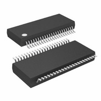
ATMEGA32HVB-8X3 Atmel, ATMEGA32HVB-8X3 Datasheet - Page 151

ATMEGA32HVB-8X3
Manufacturer Part Number
ATMEGA32HVB-8X3
Description
MCU AVR 32KB FLASH 8MHZ 44TSSOP
Manufacturer
Atmel
Series
AVR® ATmegar
Specifications of ATMEGA32HVB-8X3
Core Processor
AVR
Core Size
8-Bit
Speed
8MHz
Connectivity
I²C, SPI
Peripherals
POR, WDT
Number Of I /o
17
Program Memory Size
32KB (16K x 16)
Program Memory Type
FLASH
Eeprom Size
1K x 8
Ram Size
2K x 8
Voltage - Supply (vcc/vdd)
4 V ~ 25 V
Data Converters
A/D 7x12b
Oscillator Type
External
Operating Temperature
-40°C ~ 85°C
Package / Case
44-TSSOP
Processor Series
ATMEGA32x
Core
AVR8
Data Bus Width
8 bit
Data Ram Size
2 KB
Interface Type
SPI, TWI
Maximum Clock Frequency
8 MHz
Number Of Programmable I/os
17
Number Of Timers
2
Maximum Operating Temperature
+ 85 C
Mounting Style
SMD/SMT
Development Tools By Supplier
ATAVRDRAGON, ATSTK500, ATSTK600, ATAVRISP2, ATAVRONEKIT, ATAVRSB200
Minimum Operating Temperature
- 40 C
On-chip Adc
12 bit, 7 Channel
Package
44TSSOP
Device Core
AVR
Family Name
ATmega
Maximum Speed
8 MHz
Operating Supply Voltage
5|9|12|15|18|24 V
For Use With
ATSTK524 - KIT STARTER ATMEGA32M1/MEGA32C1ATSTK600 - DEV KIT FOR AVR/AVR32ATAVRDRAGON - KIT DRAGON 32KB FLASH MEM AVRATSTK500 - PROGRAMMER AVR STARTER KIT
Lead Free Status / RoHS Status
Lead free / RoHS Compliant
Available stocks
Company
Part Number
Manufacturer
Quantity
Price
Company:
Part Number:
ATMEGA32HVB-8X3
Manufacturer:
Atmel
Quantity:
408
- Current page: 151 of 275
- Download datasheet (7Mb)
8042B–AVR–06/10
When the battery is started from a power-off condition by connecting a legal charger, SW should
determine whether to allow charging or not before enabling the C-FET. Before allowing charging
it is recommended to use the V-ADC to measure the cell temperature and cell voltages. Depend-
ing on the total cell voltage, the device should either start up in DUVR mode or in normal
charging mode with the C-FET and D-FET enabled.
• If the total cell voltage is below 4.5V, the battery should enter DUVR charging mode. This
• If the total cell voltage is above 4.5V, the battery should enter normal charging mode with both
The
charging 3 deeply discharged Li-ion cells in series using DUVR mode.
Figure 25-3. DUVR mode charging in 3-cell mode configuration
1. A charger with 12.6V charge voltage is plugged to the Pack+ pin and the
2. The ATmega16HVB/32HVB exit reset and initializes modules. To determine if charging
3. D-FET is enabled and the VFET voltage increase to the Pack+ level.
4. DUVR mode is entered by clearing the DUVRD bit in FCSR. The VFET voltage and the
5. The total cell voltage has reached the regulated VFET limit and VFET follows the cell
ensures safe operation voltage while allowing charging.
C-FET and D-FET enabled.
need to ensure to exit DUVR mode and enable the C-FET before the charger sees this
limit.
ATmega16HVB/32HVB enters reset mode. Charger should be configured with a charge
current limit (pre-charge current).
should be allowed and if DUVR mode should be entered, cell temperature and cell volt-
ages are measured by the V-ADC.
Pack+ voltage will now be regulated to approximately 4.5V.
voltage as the battery is charged.
”DUVR mode charging in 3-cell mode configuration” on page 151
14
12
10
8
6
4
2
0
1 2
3
4
5 6
ATmega16HVB/32HVB
shows an example of
7
RESET
DUVRD
CFE
DFE
PVT
Pack+
151
Related parts for ATMEGA32HVB-8X3
Image
Part Number
Description
Manufacturer
Datasheet
Request
R

Part Number:
Description:
Manufacturer:
Atmel Corporation
Datasheet:

Part Number:
Description:
Manufacturer:
ATMEL Corporation
Datasheet:

Part Number:
Description:
IC AVR MCU 32K 16MHZ 5V 44-QFN
Manufacturer:
Atmel
Datasheet:

Part Number:
Description:
IC AVR MCU 32K 16MHZ 5V 40DIP
Manufacturer:
Atmel
Datasheet:

Part Number:
Description:
IC AVR MCU 32K 16MHZ 5V 44TQFP
Manufacturer:
Atmel
Datasheet:

Part Number:
Description:
IC AVR MCU 32K 16MHZ IND 40-DIP
Manufacturer:
Atmel
Datasheet:

Part Number:
Description:
IC AVR MCU 32K 16MHZ IND 44-TQFP
Manufacturer:
Atmel
Datasheet:

Part Number:
Description:
MCU AVR 32KB FLASH 16MHZ 44TQFP
Manufacturer:
Atmel
Datasheet:

Part Number:
Description:
MCU AVR 32KB FLASH 16MHZ 44QFN
Manufacturer:
Atmel
Datasheet:

Part Number:
Description:
MCU AVR 32K FLASH 16MHZ 44-TQFP
Manufacturer:
Atmel
Datasheet:

Part Number:
Description:
IC AVR MCU 32K 16MHZ COM 40-DIP
Manufacturer:
Atmel
Datasheet:

Part Number:
Description:
IC AVR MCU 32K 16MHZ COM 44-QFN
Manufacturer:
Atmel
Datasheet:

Part Number:
Description:
IC AVR MCU 32K 16MHZ COM 44-TQFP
Manufacturer:
Atmel
Datasheet:


