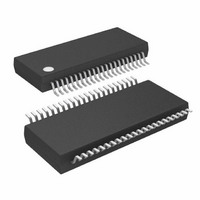
ATMEGA32HVB-8X3 Atmel, ATMEGA32HVB-8X3 Datasheet - Page 140

ATMEGA32HVB-8X3
Manufacturer Part Number
ATMEGA32HVB-8X3
Description
MCU AVR 32KB FLASH 8MHZ 44TSSOP
Manufacturer
Atmel
Series
AVR® ATmegar
Specifications of ATMEGA32HVB-8X3
Core Processor
AVR
Core Size
8-Bit
Speed
8MHz
Connectivity
I²C, SPI
Peripherals
POR, WDT
Number Of I /o
17
Program Memory Size
32KB (16K x 16)
Program Memory Type
FLASH
Eeprom Size
1K x 8
Ram Size
2K x 8
Voltage - Supply (vcc/vdd)
4 V ~ 25 V
Data Converters
A/D 7x12b
Oscillator Type
External
Operating Temperature
-40°C ~ 85°C
Package / Case
44-TSSOP
Processor Series
ATMEGA32x
Core
AVR8
Data Bus Width
8 bit
Data Ram Size
2 KB
Interface Type
SPI, TWI
Maximum Clock Frequency
8 MHz
Number Of Programmable I/os
17
Number Of Timers
2
Maximum Operating Temperature
+ 85 C
Mounting Style
SMD/SMT
Development Tools By Supplier
ATAVRDRAGON, ATSTK500, ATSTK600, ATAVRISP2, ATAVRONEKIT, ATAVRSB200
Minimum Operating Temperature
- 40 C
On-chip Adc
12 bit, 7 Channel
Package
44TSSOP
Device Core
AVR
Family Name
ATmega
Maximum Speed
8 MHz
Operating Supply Voltage
5|9|12|15|18|24 V
For Use With
ATSTK524 - KIT STARTER ATMEGA32M1/MEGA32C1ATSTK600 - DEV KIT FOR AVR/AVR32ATAVRDRAGON - KIT DRAGON 32KB FLASH MEM AVRATSTK500 - PROGRAMMER AVR STARTER KIT
Lead Free Status / RoHS Status
Lead free / RoHS Compliant
Available stocks
Company
Part Number
Manufacturer
Quantity
Price
Company:
Part Number:
ATMEGA32HVB-8X3
Manufacturer:
Atmel
Quantity:
408
- Current page: 140 of 275
- Download datasheet (7Mb)
24.6
24.7
24.7.1
8042B–AVR–06/10
Battery Protection CPU Interface
Register Description
BPPLR – Battery Protection Parameter Lock Register
The Battery Protection CPU Interface is illustrated in
Figure 24-2. Battery Protection CPU Interface
Each protection originating from the Current Battery Protection module has an Interrupt Flag.
Each Flag can be read and cleared by the CPU, and each flag has an individual interrupt enable.
All enabled flags are combined into a single battery protection interrupt request to the CPU. This
interrupt can wake up the CPU from any operation mode, except Power-off. The interrupt flags
are cleared by writing a logic ‘1’ to their bit locations from the CPU. An interrupt event for the
External Protection Input can be generated by enabling the external interrupt for the input port.
• Bit 7:2 – Reserved
These bits are reserved and will always read as zero.
• Bit 1 – BPPLE: Battery Protection Parameter Lock Enable
• Bit 0 – BPPL: Battery Protection Parameter Lock
The BPCR, BPHCTR, BPOCTR, BPSCTR, BPDHCD, BPCHCD, BPDOCD, BPCOCD and
BPSCD Battery Protection registers can be locked from any further software updates. Once
Bit
(0xFE)
Read/Write
Initial Value
Battery Protection
Parameter Lock
Register
EXTPROT
PPI
NNI
R
7
–
0
Battery Protection
Level Register
LOCK?
R
6
–
0
Battery Protection
R
Timing Register
5
–
0
Protection
Current
Battery
LOCK?
R
4
–
0
Battery Protection
Control Register
LOCK?
ATmega16HVB/32HVB
Figure 24-2 on page
R
3
–
0
Power-off
R
2
–
0
Interrupt
Request
BPPLE
Protection
R/W
Current
1
0
140.
8-BIT DATA BUS
Acknowledge
Protection
Interrupt
Interrupt
Register
10
Battery
Control
/
FET
BPPL
R/W
0
0
5
5
/
/
BPPLR
140
Related parts for ATMEGA32HVB-8X3
Image
Part Number
Description
Manufacturer
Datasheet
Request
R

Part Number:
Description:
Manufacturer:
Atmel Corporation
Datasheet:

Part Number:
Description:
Manufacturer:
ATMEL Corporation
Datasheet:

Part Number:
Description:
IC AVR MCU 32K 16MHZ 5V 44-QFN
Manufacturer:
Atmel
Datasheet:

Part Number:
Description:
IC AVR MCU 32K 16MHZ 5V 40DIP
Manufacturer:
Atmel
Datasheet:

Part Number:
Description:
IC AVR MCU 32K 16MHZ 5V 44TQFP
Manufacturer:
Atmel
Datasheet:

Part Number:
Description:
IC AVR MCU 32K 16MHZ IND 40-DIP
Manufacturer:
Atmel
Datasheet:

Part Number:
Description:
IC AVR MCU 32K 16MHZ IND 44-TQFP
Manufacturer:
Atmel
Datasheet:

Part Number:
Description:
MCU AVR 32KB FLASH 16MHZ 44TQFP
Manufacturer:
Atmel
Datasheet:

Part Number:
Description:
MCU AVR 32KB FLASH 16MHZ 44QFN
Manufacturer:
Atmel
Datasheet:

Part Number:
Description:
MCU AVR 32K FLASH 16MHZ 44-TQFP
Manufacturer:
Atmel
Datasheet:

Part Number:
Description:
IC AVR MCU 32K 16MHZ COM 40-DIP
Manufacturer:
Atmel
Datasheet:

Part Number:
Description:
IC AVR MCU 32K 16MHZ COM 44-QFN
Manufacturer:
Atmel
Datasheet:

Part Number:
Description:
IC AVR MCU 32K 16MHZ COM 44-TQFP
Manufacturer:
Atmel
Datasheet:


