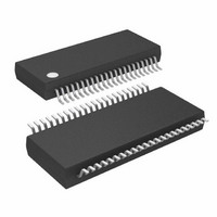
ATMEGA32HVB-8X3 Atmel, ATMEGA32HVB-8X3 Datasheet - Page 111

ATMEGA32HVB-8X3
Manufacturer Part Number
ATMEGA32HVB-8X3
Description
MCU AVR 32KB FLASH 8MHZ 44TSSOP
Manufacturer
Atmel
Series
AVR® ATmegar
Specifications of ATMEGA32HVB-8X3
Core Processor
AVR
Core Size
8-Bit
Speed
8MHz
Connectivity
I²C, SPI
Peripherals
POR, WDT
Number Of I /o
17
Program Memory Size
32KB (16K x 16)
Program Memory Type
FLASH
Eeprom Size
1K x 8
Ram Size
2K x 8
Voltage - Supply (vcc/vdd)
4 V ~ 25 V
Data Converters
A/D 7x12b
Oscillator Type
External
Operating Temperature
-40°C ~ 85°C
Package / Case
44-TSSOP
Processor Series
ATMEGA32x
Core
AVR8
Data Bus Width
8 bit
Data Ram Size
2 KB
Interface Type
SPI, TWI
Maximum Clock Frequency
8 MHz
Number Of Programmable I/os
17
Number Of Timers
2
Maximum Operating Temperature
+ 85 C
Mounting Style
SMD/SMT
Development Tools By Supplier
ATAVRDRAGON, ATSTK500, ATSTK600, ATAVRISP2, ATAVRONEKIT, ATAVRSB200
Minimum Operating Temperature
- 40 C
On-chip Adc
12 bit, 7 Channel
Package
44TSSOP
Device Core
AVR
Family Name
ATmega
Maximum Speed
8 MHz
Operating Supply Voltage
5|9|12|15|18|24 V
For Use With
ATSTK524 - KIT STARTER ATMEGA32M1/MEGA32C1ATSTK600 - DEV KIT FOR AVR/AVR32ATAVRDRAGON - KIT DRAGON 32KB FLASH MEM AVRATSTK500 - PROGRAMMER AVR STARTER KIT
Lead Free Status / RoHS Status
Lead free / RoHS Compliant
Available stocks
Company
Part Number
Manufacturer
Quantity
Price
Company:
Part Number:
ATMEGA32HVB-8X3
Manufacturer:
Atmel
Quantity:
408
- Current page: 111 of 275
- Download datasheet (7Mb)
19.6
19.7
19.7.1
8042B–AVR–06/10
Configuration and Usage
Register Description
CADCSRA – CC-ADC Control and Status Register A
While the CC-ADC is converting, the CPU can enter sleep mode and wait for an interrupt. After
adding the conversion data for the Coulomb Counting, the CPU can go back to sleep again. This
reduces the CPU workload, and allows more time spent in low power modes, reducing power
consumption.
To use the CC-ADC the bandgap voltage reference must be enabled separately, see
Reference and Temperature Sensor” on page
The CC-ADC will not consume power when CADEN is cleared. It is therefore recommended to
switch off the CC-ADC whenever the Coulomb Counter or Regular Current Detection functions
are not used. The CC-ADC is automatically disabled in Power-off mode.
After the CC-ADC is enabled by setting the CADEN bit, the first four conversions do not contain
useful data and should be ignored. This also applies after clearing the CADSE bit, or after
changing the CADPOL or CADVSE bits.
The conversion times and sampling intervals are controlled by the Ultra Low Power RC Oscilla-
tor (see
To obtain accurate coulomb counting results, the actual conversion time should be calculated.
Refer to
• Bit 7 – CADEN: CC-ADC Enable
When the CADEN bit is cleared (zero), the CC-ADC is disabled, and any ongoing conversions
will be terminated. When the CADEN bit is set (one), the CC-ADC will continuously measure the
voltage drop over the external sense resistor R
disabled.
Note that the bandgap voltage reference must be enabled separately, see
and Temperature Sensor” on page
• Bit 6 – CADPOL: CC-ADC Polarity
The CADPOL bit is used to change input sampling polarity in the Sigma Delta Modulator. Writing
this bit to one, the polaritiy will be negative. When the bit is zero, the polarity will be positive.
• Bit 5 – CADUB: CC-ADC Update Busy
The CC-ADC operates in a different clock domain than the CPU. Whenever a new value is writ-
ten to CADCSRA, CADCSRC, CADRCC or CADRDC, this value must be synchronized to the
CC-ADC clock domain. Subsequent writes to these registers will be blocked during this synchro-
nization. Synchronization of one of the registers will block updating of all the others. The CADUB
bit will be read as one while any of these registers is being synchronized, and will be read as
zero when neither register is being synchronized.
Bit
(0xE6)
Read/Write
Initial Value
”Ultra Low Power RC Oscillator” on page
”System Clock and Clock Options” on page 25
CADEN
R/W
7
0
CADPOL
R/W
6
0
CADUB
R
5
0
123.
CADAS1
R/W
4
0
123.
CADAS0
SENSE
27), and will depend on its actual frequency.
R/W
3
0
ATmega16HVB/32HVB
for details.
. In Power-off, the CC-ADC is always
CADSI1
R/W
2
0
CADSI0
R/W
1
0
”Voltage Reference
CADSE
R/W
0
0
CADCSRA
”Voltage
111
Related parts for ATMEGA32HVB-8X3
Image
Part Number
Description
Manufacturer
Datasheet
Request
R

Part Number:
Description:
Manufacturer:
Atmel Corporation
Datasheet:

Part Number:
Description:
Manufacturer:
ATMEL Corporation
Datasheet:

Part Number:
Description:
IC AVR MCU 32K 16MHZ 5V 44-QFN
Manufacturer:
Atmel
Datasheet:

Part Number:
Description:
IC AVR MCU 32K 16MHZ 5V 40DIP
Manufacturer:
Atmel
Datasheet:

Part Number:
Description:
IC AVR MCU 32K 16MHZ 5V 44TQFP
Manufacturer:
Atmel
Datasheet:

Part Number:
Description:
IC AVR MCU 32K 16MHZ IND 40-DIP
Manufacturer:
Atmel
Datasheet:

Part Number:
Description:
IC AVR MCU 32K 16MHZ IND 44-TQFP
Manufacturer:
Atmel
Datasheet:

Part Number:
Description:
MCU AVR 32KB FLASH 16MHZ 44TQFP
Manufacturer:
Atmel
Datasheet:

Part Number:
Description:
MCU AVR 32KB FLASH 16MHZ 44QFN
Manufacturer:
Atmel
Datasheet:

Part Number:
Description:
MCU AVR 32K FLASH 16MHZ 44-TQFP
Manufacturer:
Atmel
Datasheet:

Part Number:
Description:
IC AVR MCU 32K 16MHZ COM 40-DIP
Manufacturer:
Atmel
Datasheet:

Part Number:
Description:
IC AVR MCU 32K 16MHZ COM 44-QFN
Manufacturer:
Atmel
Datasheet:

Part Number:
Description:
IC AVR MCU 32K 16MHZ COM 44-TQFP
Manufacturer:
Atmel
Datasheet:


