MT48H8M32LFB5-75 IT:H Micron Technology Inc, MT48H8M32LFB5-75 IT:H Datasheet - Page 41
MT48H8M32LFB5-75 IT:H
Manufacturer Part Number
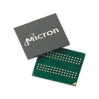
MT48H8M32LFB5-75 IT:H
Description
DRAM Chip Mobile SDRAM 256M-Bit 8Mx32 1.8V 90-Pin VFBGA Tray
Manufacturer
Micron Technology Inc
Type
Mobile SDRAMr
Specifications of MT48H8M32LFB5-75 IT:H
Density
256 Mb
Maximum Clock Rate
133 MHz
Package
90VFBGA
Address Bus Width
14 Bit
Operating Supply Voltage
1.8 V
Maximum Random Access Time
8|6 ns
Operating Temperature
-40 to 85 °C
Format - Memory
RAM
Memory Type
Mobile SDRAM
Memory Size
256M (8Mx32)
Speed
133MHz
Interface
Parallel
Voltage - Supply
1.7 V ~ 1.95 V
Package / Case
90-VFBGA
Organization
8Mx32
Address Bus
14b
Access Time (max)
8/6ns
Operating Supply Voltage (typ)
1.8V
Package Type
VFBGA
Operating Temp Range
-40C to 85C
Operating Supply Voltage (max)
1.95V
Operating Supply Voltage (min)
1.7V
Supply Current
100mA
Pin Count
90
Mounting
Surface Mount
Operating Temperature Classification
Industrial
Lead Free Status / RoHS Status
Lead free / RoHS Compliant


Burst Length
Burst Type
PDF: 09005aef834c13d2
256mb_mobile_sdram_y36n.pdf - Rev. I 11/09 EN
Read and write accesses to the device are burst oriented, and the burst length (BL) is
programmable. The burst length determines the maximum number of column loca-
tions that can be accessed for a given READ or WRITE command. Burst lengths of 1, 2,
4, 8, or continuous locations are available for both the sequential and the interleaved
burst types, and a continuous page burst is available for the sequential type. The contin-
uous page burst is used in conjunction with the BURST TERMINATE command to
generate arbitrary burst lengths.
Reserved states should not be used, as unknown operation or incompatibility with fu-
ture versions may result.
When a READ or WRITE command is issued, a block of columns equal to the burst
length is effectively selected. All accesses for that burst take place within this block,
meaning that the burst wraps within the block when a boundary is reached. The block
is uniquely selected by A[8:1] when BL = 2, A[8:2] when BL = 4, and A[8:3] when BL = 8.
The remaining (least significant) address bit(s) is (are) used to select the starting loca-
tion within the block. Continuous page bursts wrap within the page when the boundary
is reached.
Accesses within a given burst can be programmed to be either sequential or interleaved;
this is referred to as the burst type and is selected via bit M3.
The ordering of accesses within a burst is determined by the burst length, the burst
type, and the starting column address.
256Mb: 16 Meg x 16, 8 Meg x 32 Mobile SDRAM
41
Micron Technology, Inc. reserves the right to change products or specifications without notice.
©2008 Micron Technology, Inc. All rights reserved.
Mode Register
Related parts for MT48H8M32LFB5-75 IT:H
Image
Part Number
Description
Manufacturer
Datasheet
Request
R

Part Number:
Description:
IC SDRAM 64MBIT 133MHZ 54TSOP
Manufacturer:
Micron Technology Inc
Datasheet:

Part Number:
Description:
IC SDRAM 64MBIT 5.5NS 86TSOP
Manufacturer:
Micron Technology Inc
Datasheet:
Part Number:
Description:
IC SDRAM 64MBIT 200MHZ 86TSOP
Manufacturer:
Micron Technology Inc
Datasheet:
Part Number:
Description:
IC SDRAM 64MBIT 133MHZ 54TSOP
Manufacturer:
Micron Technology Inc
Datasheet:
Part Number:
Description:
IC SDRAM 128MBIT 133MHZ 54TSOP
Manufacturer:
Micron Technology Inc
Datasheet:

Part Number:
Description:
IC SDRAM 256MBIT 133MHZ 90VFBGA
Manufacturer:
Micron Technology Inc
Datasheet:
Part Number:
Description:
IC SDRAM 128MBIT 133MHZ 54TSOP
Manufacturer:
Micron Technology Inc
Datasheet:
Part Number:
Description:
IC SDRAM 256MBIT 133MHZ 54TSOP
Manufacturer:
Micron Technology Inc
Datasheet:

Part Number:
Description:
IC DDR SDRAM 512MBIT 6NS 66TSOP
Manufacturer:
Micron Technology Inc
Datasheet:
Part Number:
Description:
IC SDRAM 128MBIT 167MHZ 86TSOP
Manufacturer:
Micron Technology Inc
Datasheet:
Part Number:
Description:
IC SDRAM 128MBIT 143MHZ 86TSOP
Manufacturer:
Micron Technology Inc
Datasheet:

Part Number:
Description:
SDRAM 256M-BIT 1.8V 54-PIN VFBGA
Manufacturer:
Micron Technology Inc
Datasheet:
Part Number:
Description:
IC SDRAM 128MBIT 143MHZ 86TSOP
Manufacturer:
Micron Technology Inc
Datasheet:

Part Number:
Description:
IC SDRAM 128MBIT 125MHZ 54VFBGA
Manufacturer:
Micron Technology Inc
Datasheet:
Part Number:
Description:
IC SDRAM 128MBIT 125MHZ 54VFBGA
Manufacturer:
Micron Technology Inc
Datasheet: