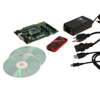
DV164136 Microchip Technology, DV164136 Datasheet - Page 82

DV164136
Manufacturer Part Number
DV164136
Description
DEVELOPMENT KIT FOR PIC18
Manufacturer
Microchip Technology
Series
PIC®r
Type
MCUr
Datasheets
1.DM183032.pdf
(38 pages)
2.DV164136.pdf
(448 pages)
3.DV164136.pdf
(6 pages)
4.DV164136.pdf
(446 pages)
5.DV164136.pdf
(4 pages)
6.DV164136.pdf
(18 pages)
Specifications of DV164136
Contents
Board, Cables, CDs, PICkit™ 3 Programmer, Power Supply
Processor To Be Evaluated
PIC18F8722, PIC18F87J11
Interface Type
RS-232, USB
Operating Supply Voltage
3.3 V, 5 V
Silicon Manufacturer
Microchip
Core Architecture
PIC
Core Sub-architecture
PIC18
Silicon Core Number
PIC18F
Silicon Family Name
PIC18F8xxx
Kit Contents
PIC18 Exp Brd PICkit 3 Cable CD PSU
Lead Free Status / RoHS Status
Lead free / RoHS Compliant
For Use With/related Products
PIC18F8722, PIC18F87J11
Lead Free Status / Rohs Status
Lead free / RoHS Compliant
Available stocks
Company
Part Number
Manufacturer
Quantity
Price
Company:
Part Number:
DV164136
Manufacturer:
MICROCHIP
Quantity:
12 000
- DM183032 PDF datasheet
- DV164136 PDF datasheet #2
- DV164136 PDF datasheet #3
- DV164136 PDF datasheet #4
- DV164136 PDF datasheet #5
- DV164136 PDF datasheet #6
- Current page: 82 of 446
- Download datasheet (7Mb)
PIC18F8722 FAMILY
5.3.5
The STATUS register, shown in Register 5-2, contains
the arithmetic status of the ALU. As with any other SFR,
it can be the operand for any instruction.
If the STATUS register is the destination for an instruction
that affects the Z, DC, C, OV or N bits, the results of the
instruction are not written; instead, the STATUS register
is updated according to the instruction performed. There-
fore, the result of an instruction with the STATUS register
as its destination may be different than intended. As an
example, CLRF STATUS will set the Z bit and leave the
remaining Status bits unchanged (‘000u u1uu’).
REGISTER 5-2:
DS39646C-page 80
bit 7
Legend:
R = Readable bit
-n = Value at POR
bit 7-5
bit 4
bit 3
bit 2
bit 1
bit 0
Note 1:
U-0
—
2:
For borrow, the polarity is reversed. A subtraction is executed by adding the 2’s complement of the second
operand. For rotate (RRF, RLF) instructions, this bit is loaded with either bit 4 or bit 3 of the source register.
For borrow, the polarity is reversed. A subtraction is executed by adding the 2’s complement of the second
operand. For rotate (RRF, RLF) instructions, this bit is loaded with either the high or low-order bit of the
source register.
STATUS REGISTER
Unimplemented: Read as ‘0’
N: Negative bit
This bit is used for signed arithmetic (2’s complement). It indicates whether the result was
1 = Result was negative
0 = Result was positive
OV: Overflow bit
This bit is used for signed arithmetic (2’s complement). It indicates an overflow of the 7-bit
magnitude which causes the sign bit (bit 7 of the result) to change state.
1 = Overflow occurred for signed arithmetic (in this arithmetic operation)
0 = No overflow occurred
Z: Zero bit
1 = The result of an arithmetic or logic operation is zero
0 = The result of an arithmetic or logic operation is not zero
DC: Digit Carry/borrow bit
For ADDWF, ADDLW, SUBLW and SUBWF instructions:
1 = A carry-out from the 4th low-order bit of the result occurred
0 = No carry-out from the 4th low-order bit of the result
C: Carry/borrow bit
For ADDWF, ADDLW, SUBLW and SUBWF instructions:
1 = A carry-out from the Most Significant bit of the result occurred
0 = No carry-out from the Most Significant bit of the result occurred
negative (ALU MSB = 1).
U-0
—
STATUS: ARITHMETIC STATUS REGISTER
W = Writable bit
‘1’ = Bit is set
(2)
U-0
—
(1)
R/W-x
N
U = Unimplemented bit, read as ‘0’
‘0’ = Bit is cleared
R/W-x
It is recommended that only BCF, BSF, SWAPF, MOVFF
and MOVWF instructions are used to alter the STATUS
register, because these instructions do not affect the Z,
C, DC, OV or N bits in the STATUS register.
For other instructions that do not affect Status bits, see
the instruction set summaries in Table 26-2 and
Table 26-3.
OV
Note:
The C and DC bits operate as the borrow
and digit borrow bits, respectively, in
subtraction.
R/W-x
Z
© 2008 Microchip Technology Inc.
x = Bit is unknown
R/W-x
DC
(1)
R/W-x
C
(2)
bit 0
Related parts for DV164136
Image
Part Number
Description
Manufacturer
Datasheet
Request
R

Part Number:
Description:
Manufacturer:
Microchip Technology Inc.
Datasheet:

Part Number:
Description:
Manufacturer:
Microchip Technology Inc.
Datasheet:

Part Number:
Description:
Manufacturer:
Microchip Technology Inc.
Datasheet:

Part Number:
Description:
Manufacturer:
Microchip Technology Inc.
Datasheet:

Part Number:
Description:
Manufacturer:
Microchip Technology Inc.
Datasheet:

Part Number:
Description:
Manufacturer:
Microchip Technology Inc.
Datasheet:

Part Number:
Description:
Manufacturer:
Microchip Technology Inc.
Datasheet:

Part Number:
Description:
Manufacturer:
Microchip Technology Inc.
Datasheet:


