Z8F64220100ZDA Zilog, Z8F64220100ZDA Datasheet - Page 96
Z8F64220100ZDA
Manufacturer Part Number
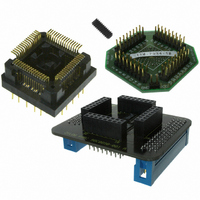
Z8F64220100ZDA
Description
ADAPTER ICE Z8 ENCORE 64K 64LQFP
Manufacturer
Zilog
Specifications of Z8F64220100ZDA
Module/board Type
*
For Use With/related Products
Z8 Encore!™
Lead Free Status / RoHS Status
Contains lead / RoHS non-compliant
Other names
269-3403


PS019921-0308
Follow the steps below for configuring a timer for PWM mode and initiating the PWM
operation:
1. Write to the Timer Control 1 register to:
2. Write to the Timer High and Low Byte registers to set the starting count value
3. Write to the PWM High and Low Byte registers to set the PWM value.
4. Write to the Timer Reload High and Low Byte registers to set the Reload value (PWM
5. If desired, enable the timer interrupt and set the timer interrupt priority by writing to
6. Configure the associated GPIO port pin for the Timer Output alternate function.
7. Write to the Timer Control 1 register to enable the timer and initiate counting.
The PWM period is given by the following equation:
If an initial starting value other than
registers, the ONE-SHOT mode equation must be used to determine the first PWM time-
out period.
If TPOL is set to 0, the ratio of the PWM output High time to the total period is given by:
If TPOL is set to 1, the ratio of the PWM output High time to the total period is given by:
CAPTURE Mode
In CAPTURE mode, the current timer count value is recorded when the desired external
Timer Input transition occurs. The Capture count value is written to the Timer PWM High
and Low Byte Registers. The timer input is the system clock. The TPOL bit in the Timer
Control 1 register determines if the Capture occurs on a rising edge or a falling edge of the
Timer Input signal. When the Capture event occurs, an interrupt is generated and the timer
continues counting.
PWM Period (s)
PWM Output High Time Ratio (%)
PWM Output High Time Ratio (%)
–
–
–
–
(typically
reset in PWM mode, counting always begins at the reset value of
period). The Reload value must be greater than the PWM value.
the relevant interrupt registers.
Disable the timer
Configure the timer for PWM mode
Set the prescale value
Set the initial logic level (High or Low) and PWM High/Low transition for the
Timer Output alternate function
0001H
=
------------------------------------------------------------------------
System Clock Frequency (Hz)
). This only affects the first pass in PWM mode. After the first timer
Reload Value
=
=
×
Prescale
--------------------------------
Reload Value
Reload Value PWM Value
-------------------------------------------------------------------- -
0001H
PWM Value
Reload Value
is loaded into the Timer High and Low Byte
×
–
100
Z8 Encore! XP
×
Product Specification
100
0001H
®
F64XX Series
.
Timers
82
Related parts for Z8F64220100ZDA
Image
Part Number
Description
Manufacturer
Datasheet
Request
R

Part Number:
Description:
Communication Controllers, ZILOG INTELLIGENT PERIPHERAL CONTROLLER (ZIP)
Manufacturer:
Zilog, Inc.
Datasheet:

Part Number:
Description:
KIT DEV FOR Z8 ENCORE 16K TO 64K
Manufacturer:
Zilog
Datasheet:

Part Number:
Description:
KIT DEV Z8 ENCORE XP 28-PIN
Manufacturer:
Zilog
Datasheet:

Part Number:
Description:
DEV KIT FOR Z8 ENCORE 8K/4K
Manufacturer:
Zilog
Datasheet:

Part Number:
Description:
KIT DEV Z8 ENCORE XP 28-PIN
Manufacturer:
Zilog
Datasheet:

Part Number:
Description:
DEV KIT FOR Z8 ENCORE 4K TO 8K
Manufacturer:
Zilog
Datasheet:
Part Number:
Description:
CMOS Z8 microcontroller. ROM 16 Kbytes, RAM 256 bytes, speed 16 MHz, 32 lines I/O, 3.0V to 5.5V
Manufacturer:
Zilog, Inc.
Datasheet:
Part Number:
Description:
Low-cost microcontroller. 512 bytes ROM, 61 bytes RAM, 8 MHz
Manufacturer:
Zilog, Inc.
Datasheet:
Part Number:
Description:
Z8 4K OTP Microcontroller
Manufacturer:
Zilog, Inc.
Datasheet:
Part Number:
Description:
CMOS SUPER8 ROMLESS MCU
Manufacturer:
Zilog, Inc.
Datasheet:
Part Number:
Description:
SL1866 CMOSZ8 OTP Microcontroller
Manufacturer:
Zilog, Inc.
Datasheet:
Part Number:
Description:
SL1866 CMOSZ8 OTP Microcontroller
Manufacturer:
Zilog, Inc.
Datasheet:
Part Number:
Description:
OTP (KB) = 1, RAM = 125, Speed = 12, I/O = 14, 8-bit Timers = 2, Comm Interfaces Other Features = Por, LV Protect, Voltage = 4.5-5.5V
Manufacturer:
Zilog, Inc.
Datasheet:
Part Number:
Description:
Manufacturer:
Zilog, Inc.
Datasheet: