Z8F64220100ZDA Zilog, Z8F64220100ZDA Datasheet - Page 119
Z8F64220100ZDA
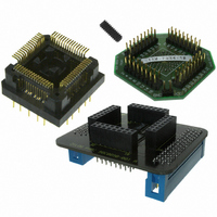
Manufacturer Part Number
Z8F64220100ZDA
Description
ADAPTER ICE Z8 ENCORE 64K 64LQFP
Manufacturer
Zilog
Specifications of Z8F64220100ZDA
Module/board Type
*
For Use With/related Products
Z8 Encore!™
Lead Free Status / RoHS Status
Contains lead / RoHS non-compliant
Other names
269-3403


PS019921-0308
1
0
Idle State
of Line
Clear To Send (CTS) Operation
MULTIPROCESSOR (9-bit) Mode
Figure 15. UART Asynchronous MULTIPROCESSOR Mode Data Format
3. Clear the UART Receiver interrupt in the applicable Interrupt Request register.
4. Execute the IRET instruction to return from the interrupt-service routine and await
The CTS pin, if enabled by the CTSE bit of the UART Control 0 register, performs flow
control on the outgoing transmit datastream. The Clear To Send (CTS) input pin is sam-
pled one system clock before beginning any new character transmission. To delay trans-
mission of the next data character, an external receiver must deassert CTS at least one
system clock cycle before a new data transmission begins. For multiple character trans-
missions, this would typically be done during Stop Bit transmission. If CTS deasserts in
the middle of a character transmission, the current character is sent completely.
The UART has a MULTIPROCESSOR (9-bit) mode that uses an extra (9th) bit for selec-
tive communication when a number of processors share a common UART bus. In MULTI-
PROCESSOR mode (also referred to as 9-Bit mode), the multiprocessor bit (MP) is
transmitted immediately following the 8-bits of data and immediately preceding the Stop
bit(s) as displayed in
In MULTIPROCESSOR (9-bit) mode, the Parity bit location (9th bit) becomes the MUL-
TIPROCESSOR control bit. The UART Control 1 and Status 1 registers provide MULTI-
PROCESSOR (9-bit) mode control and status information. If an automatic address
matching scheme is enabled, the UART Address Compare register holds the network
address of the device.
MULTIPROCESSOR (9-bit) Mode Receive Interrupts
When MULTIPROCESSOR mode is enabled, the UART only processes frames addressed
to it. The determination of whether a frame of data is addressed to the UART can be made
in hardware, software or some combination of the two, depending on the multiprocessor
Start
more data.
Bit0
lsb
Bit1
Figure
Bit2
15. The character format is:
Bit3
Data Field
Bit4
Bit5
Bit6
Z8 Encore! XP
msb
Bit7
Product Specification
MP
®
F64XX Series
1
Stop Bit(s)
2
UART
105
Related parts for Z8F64220100ZDA
Image
Part Number
Description
Manufacturer
Datasheet
Request
R

Part Number:
Description:
Communication Controllers, ZILOG INTELLIGENT PERIPHERAL CONTROLLER (ZIP)
Manufacturer:
Zilog, Inc.
Datasheet:

Part Number:
Description:
KIT DEV FOR Z8 ENCORE 16K TO 64K
Manufacturer:
Zilog
Datasheet:

Part Number:
Description:
KIT DEV Z8 ENCORE XP 28-PIN
Manufacturer:
Zilog
Datasheet:

Part Number:
Description:
DEV KIT FOR Z8 ENCORE 8K/4K
Manufacturer:
Zilog
Datasheet:

Part Number:
Description:
KIT DEV Z8 ENCORE XP 28-PIN
Manufacturer:
Zilog
Datasheet:

Part Number:
Description:
DEV KIT FOR Z8 ENCORE 4K TO 8K
Manufacturer:
Zilog
Datasheet:
Part Number:
Description:
CMOS Z8 microcontroller. ROM 16 Kbytes, RAM 256 bytes, speed 16 MHz, 32 lines I/O, 3.0V to 5.5V
Manufacturer:
Zilog, Inc.
Datasheet:
Part Number:
Description:
Low-cost microcontroller. 512 bytes ROM, 61 bytes RAM, 8 MHz
Manufacturer:
Zilog, Inc.
Datasheet:
Part Number:
Description:
Z8 4K OTP Microcontroller
Manufacturer:
Zilog, Inc.
Datasheet:
Part Number:
Description:
CMOS SUPER8 ROMLESS MCU
Manufacturer:
Zilog, Inc.
Datasheet:
Part Number:
Description:
SL1866 CMOSZ8 OTP Microcontroller
Manufacturer:
Zilog, Inc.
Datasheet:
Part Number:
Description:
SL1866 CMOSZ8 OTP Microcontroller
Manufacturer:
Zilog, Inc.
Datasheet:
Part Number:
Description:
OTP (KB) = 1, RAM = 125, Speed = 12, I/O = 14, 8-bit Timers = 2, Comm Interfaces Other Features = Por, LV Protect, Voltage = 4.5-5.5V
Manufacturer:
Zilog, Inc.
Datasheet:
Part Number:
Description:
Manufacturer:
Zilog, Inc.
Datasheet: