Z8F64220100ZDA Zilog, Z8F64220100ZDA Datasheet - Page 137
Z8F64220100ZDA
Manufacturer Part Number
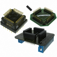
Z8F64220100ZDA
Description
ADAPTER ICE Z8 ENCORE 64K 64LQFP
Manufacturer
Zilog
Specifications of Z8F64220100ZDA
Module/board Type
*
For Use With/related Products
Z8 Encore!™
Lead Free Status / RoHS Status
Contains lead / RoHS non-compliant
Other names
269-3403


PS019921-0308
Baud Rate
IR_RXD
UART’s
Clock
RXD
Caution:
8-clock
delay
Start Bit = 0
When the Infrared Endec is enabled, the UART’s RXD signal is internal to the Z8 Encore!
XP
Endec Receiver Synchronization
The IrDA receiver uses a local baud rate clock counter (0 to 15 clock periods) to generate
an input stream for the UART and to create a sampling window for detection of incoming
pulses. The generated UART input (UART RXD) is delayed by 8 baud rate clock periods
with respect to the incoming IrDA data stream. When a falling edge in the input data
stream is detected, the Endec counter is reset. When the count reaches a value of 8, the
UART RXD value is updated to reflect the value of the decoded data. When the count
reaches 12 baud clock periods, the sampling window for the next incoming pulse opens.
The window remains open until the count again reaches 8 (or in other words 24 baud clock
periods since the previous pulse was detected). This gives the Endec a sampling window
of minus four baudrate clocks to plus eight baudrate clocks around the expected time of an
incoming pulse. If an incoming pulse is detected inside this window this process is
repeated. If the incoming data is a logical 1 (no pulse), the Endec returns to the initial state
and waits for the next falling edge. As each falling edge is detected, the Endec clock
counter is reset, resynchronizing the Endec to the incoming signal. This action allows the
Endec to tolerate jitter and baud rate errors in the incoming data stream. Resynchronizing
the Endec does not alter the operation of the UART, which ultimately receives the data.
The UART is only synchronized to the incoming data stream when a Start bit is received.
16-clock
min. 1.6
period
®
The system clock frequency must be at least 1.0 MHz to ensure proper recep-
tion of the 1.6
pulse
F64XX Series products while the IR_RXD signal is received through the
Start Bit = 0
µ
16-clock
s
period
Data Bit 0 = 1
Figure 20. Infrared Data Reception
µ
s minimum width pulses allowed by the IrDA standard.
Data Bit 0 = 1
16-clock
period
Data Bit 1 = 0
Data Bit 1 = 0
16-clock
period
Data Bit 2 = 1
Z8 Encore! XP
Data Bit 2 = 1
16-clock
period
Product Specification
Infrared Encoder/Decoder
Data Bit 3 = 1
®
F64XX Series
Data Bit 3 = 1
RXD
pin.
123
Related parts for Z8F64220100ZDA
Image
Part Number
Description
Manufacturer
Datasheet
Request
R

Part Number:
Description:
Communication Controllers, ZILOG INTELLIGENT PERIPHERAL CONTROLLER (ZIP)
Manufacturer:
Zilog, Inc.
Datasheet:

Part Number:
Description:
KIT DEV FOR Z8 ENCORE 16K TO 64K
Manufacturer:
Zilog
Datasheet:

Part Number:
Description:
KIT DEV Z8 ENCORE XP 28-PIN
Manufacturer:
Zilog
Datasheet:

Part Number:
Description:
DEV KIT FOR Z8 ENCORE 8K/4K
Manufacturer:
Zilog
Datasheet:

Part Number:
Description:
KIT DEV Z8 ENCORE XP 28-PIN
Manufacturer:
Zilog
Datasheet:

Part Number:
Description:
DEV KIT FOR Z8 ENCORE 4K TO 8K
Manufacturer:
Zilog
Datasheet:
Part Number:
Description:
CMOS Z8 microcontroller. ROM 16 Kbytes, RAM 256 bytes, speed 16 MHz, 32 lines I/O, 3.0V to 5.5V
Manufacturer:
Zilog, Inc.
Datasheet:
Part Number:
Description:
Low-cost microcontroller. 512 bytes ROM, 61 bytes RAM, 8 MHz
Manufacturer:
Zilog, Inc.
Datasheet:
Part Number:
Description:
Z8 4K OTP Microcontroller
Manufacturer:
Zilog, Inc.
Datasheet:
Part Number:
Description:
CMOS SUPER8 ROMLESS MCU
Manufacturer:
Zilog, Inc.
Datasheet:
Part Number:
Description:
SL1866 CMOSZ8 OTP Microcontroller
Manufacturer:
Zilog, Inc.
Datasheet:
Part Number:
Description:
SL1866 CMOSZ8 OTP Microcontroller
Manufacturer:
Zilog, Inc.
Datasheet:
Part Number:
Description:
OTP (KB) = 1, RAM = 125, Speed = 12, I/O = 14, 8-bit Timers = 2, Comm Interfaces Other Features = Por, LV Protect, Voltage = 4.5-5.5V
Manufacturer:
Zilog, Inc.
Datasheet:
Part Number:
Description:
Manufacturer:
Zilog, Inc.
Datasheet: