Z8F64220100ZDA Zilog, Z8F64220100ZDA Datasheet - Page 155
Z8F64220100ZDA
Manufacturer Part Number
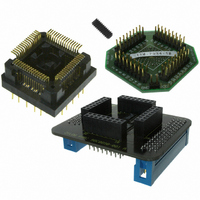
Z8F64220100ZDA
Description
ADAPTER ICE Z8 ENCORE 64K 64LQFP
Manufacturer
Zilog
Specifications of Z8F64220100ZDA
Module/board Type
*
For Use With/related Products
Z8 Encore!™
Lead Free Status / RoHS Status
Contains lead / RoHS non-compliant
Other names
269-3403


PS019921-0308
SDA and SCL Signals
I
2
C Interrupts
•
•
I
bit first. SCL is the common clock for the I
alternate functions are selected for their respective GPIO ports, the pins are automatically
configured for open-drain operation.
The master (I
can become skewed by a slow slave device. During the low period of the clock, the slave
pulls the SCL signal Low to suspend the transaction. The master releases the clock at the
end of the low period and notices that the clock remains low instead of returning to a high
level. When the slave releases the clock, the I
data is transferred in bytes and there is no limit to the amount of data transferred in one
operation. When transmitting data or acknowledging read data from the slave, the SDA
signal changes in the middle of the low period of SCL and is sampled in the middle of the
high period of SCL.
The I
Acknowledge and baud rate generator. These four interrupt sources are combined into a
single interrupt request signal to the Interrupt Controller. The Transmit interrupt is enabled
by the IEN and TXI bits of the Control register. The Receive and Not Acknowledge
interrupts are enabled by the IEN bit of the Control register. The baud rate generator
interrupt is enabled by the BIRQ and IEN bits of the Control register.
Not Acknowledge interrupts occur when a Not Acknowledge condition is received from
the slave or sent by the I
Acknowledge event sets the NCKI bit of the I
setting the
I
action. In an interrupt service routine, the NCKI bit should always be checked prior to
servicing transmit or receive interrupt conditions because it indicates the transaction is
being terminated.
Receive interrupts occur when a byte of data has been received by the I
(master reading data from slave). This procedure sets the RDRF bit of the I
register. The RDRF bit is cleared by reading the I
during the acknowledge phase. The I
until the receive interrupt is cleared before performing any other action.
2
2
C sends all addresses, data and acknowledge signals over the SDA line, most-significant
C Controller waits until either the STOP or START bit is set before performing any
Master receives from a 7-bit slave
Master receives from a 10-bit slave
2
C Controller contains four sources of interrupts—Transmit, Receive, Not
START
2
C) is responsible for driving the SCL clock signal, although the clock signal
or
STOP
2
C Controller and neither the
bit in the I
2
2
C Controller pauses after the acknowledge phase
C Control register. When this interrupt occurs, the
2
C Controller. When the SDA and SCL pin
2
2
C Status register and can only be cleared by
C Controller continues the transaction. All
2
C Data register. The RDRF bit is set
START
Z8 Encore! XP
or
STOP
Product Specification
bit is set. The Not
2
®
C Controller
F64XX Series
2
C Status
I2C Controller
141
Related parts for Z8F64220100ZDA
Image
Part Number
Description
Manufacturer
Datasheet
Request
R

Part Number:
Description:
Communication Controllers, ZILOG INTELLIGENT PERIPHERAL CONTROLLER (ZIP)
Manufacturer:
Zilog, Inc.
Datasheet:

Part Number:
Description:
KIT DEV FOR Z8 ENCORE 16K TO 64K
Manufacturer:
Zilog
Datasheet:

Part Number:
Description:
KIT DEV Z8 ENCORE XP 28-PIN
Manufacturer:
Zilog
Datasheet:

Part Number:
Description:
DEV KIT FOR Z8 ENCORE 8K/4K
Manufacturer:
Zilog
Datasheet:

Part Number:
Description:
KIT DEV Z8 ENCORE XP 28-PIN
Manufacturer:
Zilog
Datasheet:

Part Number:
Description:
DEV KIT FOR Z8 ENCORE 4K TO 8K
Manufacturer:
Zilog
Datasheet:
Part Number:
Description:
CMOS Z8 microcontroller. ROM 16 Kbytes, RAM 256 bytes, speed 16 MHz, 32 lines I/O, 3.0V to 5.5V
Manufacturer:
Zilog, Inc.
Datasheet:
Part Number:
Description:
Low-cost microcontroller. 512 bytes ROM, 61 bytes RAM, 8 MHz
Manufacturer:
Zilog, Inc.
Datasheet:
Part Number:
Description:
Z8 4K OTP Microcontroller
Manufacturer:
Zilog, Inc.
Datasheet:
Part Number:
Description:
CMOS SUPER8 ROMLESS MCU
Manufacturer:
Zilog, Inc.
Datasheet:
Part Number:
Description:
SL1866 CMOSZ8 OTP Microcontroller
Manufacturer:
Zilog, Inc.
Datasheet:
Part Number:
Description:
SL1866 CMOSZ8 OTP Microcontroller
Manufacturer:
Zilog, Inc.
Datasheet:
Part Number:
Description:
OTP (KB) = 1, RAM = 125, Speed = 12, I/O = 14, 8-bit Timers = 2, Comm Interfaces Other Features = Por, LV Protect, Voltage = 4.5-5.5V
Manufacturer:
Zilog, Inc.
Datasheet:
Part Number:
Description:
Manufacturer:
Zilog, Inc.
Datasheet: