Z8F64220100ZDA Zilog, Z8F64220100ZDA Datasheet - Page 63
Z8F64220100ZDA
Manufacturer Part Number
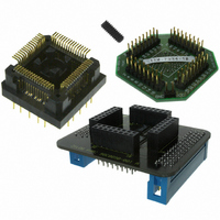
Z8F64220100ZDA
Description
ADAPTER ICE Z8 ENCORE 64K 64LQFP
Manufacturer
Zilog
Specifications of Z8F64220100ZDA
Module/board Type
*
For Use With/related Products
Z8 Encore!™
Lead Free Status / RoHS Status
Contains lead / RoHS non-compliant
Other names
269-3403


Stop Mode Recovery
PS019921-0308
External Pin Reset
On-Chip Debugger Initiated Reset
(unprogrammed) setting of the WDT_RES Option Bit. The
Control register is set to signify that the reset was initiated by the Watchdog Timer.
The RESET pin has a Schmitt-triggered input, an internal pull-up, an analog filter and a
digital filter to reject noise. Once the RESET pin is asserted for at least 4 system clock
cycles, the devices progress through the system reset sequence. While the RESET input
pin is asserted Low, the Z8 Encore! XP F64XX Series devices continue to be held in the
Reset state. If the RESET pin is held Low beyond the system reset time-out, the devices
exit the Reset state immediately following RESET pin deassertion. Following a system
reset initiated by the external RESET pin, the EXT status bit in the Watchdog Timer Con-
trol (WDTCTL) register is set to 1.
A Power-On Reset can be initiated using the On-Chip Debugger by setting the
the OCD Control register. The On-Chip Debugger block is not reset but the rest of the chip
goes through a normal system reset. The
reset. Following the system reset the
STOP mode is entered by the eZ8 executing a
information, see
are held in reset for 66 cycles of the Watchdog Timer oscillator followed by 16 cycles of
the system clock. Stop Mode Recovery only affects the contents of the Watchdog Timer
Control register. Stop Mode Recovery does not affect any other values in the Register File,
including the Stack Pointer, Register Pointer, Flags, peripheral control registers, and
general-purpose RAM.
The eZ8
and loads that value into the Program Counter. Program execution begins at the Reset
vector address. Following Stop Mode Recovery, the STOP bit in the Watchdog Timer
Control Register is set to 1.
actions.
™
CPU fetches the Reset vector at Program Memory addresses
Low-Power Modes
Table 10
on page 45. During Stop Mode Recovery, the devices
POR
lists the Stop Mode Recovery sources and resulting
RST
bit in the WDT Control register is set.
bit automatically clears during the system
STOP
instruction. For detailed STOP mode
Z8 Encore! XP
WDT
Reset and Stop Mode Recovery
status bit in the WDT
Product Specification
0002H
®
F64XX Series
and
RST
0003H
bit in
49
Related parts for Z8F64220100ZDA
Image
Part Number
Description
Manufacturer
Datasheet
Request
R

Part Number:
Description:
Communication Controllers, ZILOG INTELLIGENT PERIPHERAL CONTROLLER (ZIP)
Manufacturer:
Zilog, Inc.
Datasheet:

Part Number:
Description:
KIT DEV FOR Z8 ENCORE 16K TO 64K
Manufacturer:
Zilog
Datasheet:

Part Number:
Description:
KIT DEV Z8 ENCORE XP 28-PIN
Manufacturer:
Zilog
Datasheet:

Part Number:
Description:
DEV KIT FOR Z8 ENCORE 8K/4K
Manufacturer:
Zilog
Datasheet:

Part Number:
Description:
KIT DEV Z8 ENCORE XP 28-PIN
Manufacturer:
Zilog
Datasheet:

Part Number:
Description:
DEV KIT FOR Z8 ENCORE 4K TO 8K
Manufacturer:
Zilog
Datasheet:
Part Number:
Description:
CMOS Z8 microcontroller. ROM 16 Kbytes, RAM 256 bytes, speed 16 MHz, 32 lines I/O, 3.0V to 5.5V
Manufacturer:
Zilog, Inc.
Datasheet:
Part Number:
Description:
Low-cost microcontroller. 512 bytes ROM, 61 bytes RAM, 8 MHz
Manufacturer:
Zilog, Inc.
Datasheet:
Part Number:
Description:
Z8 4K OTP Microcontroller
Manufacturer:
Zilog, Inc.
Datasheet:
Part Number:
Description:
CMOS SUPER8 ROMLESS MCU
Manufacturer:
Zilog, Inc.
Datasheet:
Part Number:
Description:
SL1866 CMOSZ8 OTP Microcontroller
Manufacturer:
Zilog, Inc.
Datasheet:
Part Number:
Description:
SL1866 CMOSZ8 OTP Microcontroller
Manufacturer:
Zilog, Inc.
Datasheet:
Part Number:
Description:
OTP (KB) = 1, RAM = 125, Speed = 12, I/O = 14, 8-bit Timers = 2, Comm Interfaces Other Features = Por, LV Protect, Voltage = 4.5-5.5V
Manufacturer:
Zilog, Inc.
Datasheet:
Part Number:
Description:
Manufacturer:
Zilog, Inc.
Datasheet: