Z8F64220100ZDA Zilog, Z8F64220100ZDA Datasheet - Page 197
Z8F64220100ZDA
Manufacturer Part Number
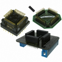
Z8F64220100ZDA
Description
ADAPTER ICE Z8 ENCORE 64K 64LQFP
Manufacturer
Zilog
Specifications of Z8F64220100ZDA
Module/board Type
*
For Use With/related Products
Z8 Encore!™
Lead Free Status / RoHS Status
Contains lead / RoHS non-compliant
Other names
269-3403


®
Z8 Encore! XP
F64XX Series
Product Specification
183
3. Write the first unlock command 73H to the Flash Control register.
4. Write the second unlock command 8CH to the Flash Control register.
5. Re-write the page written in
step 2
to the Page Select register.
Flash Sector Protection
The Flash Sector Protect register can be configured to prevent sectors from being
programmed or erased. Once a sector is protected, it cannot be unprotected by user code.
The Flash Sector Protect register is cleared after reset and any previously written
protection values is lost. User code must write this register in their initialization routine if
they want to enable sector protection.
The Flash Sector Protect register shares its Register File address with the Page Select
register. The Flash Sector Protect register is accessed by writing the Flash Control register
with 5EH. Once the Flash Sector Protect register is selected, it can be accessed at the Page
Select Register address. When user code writes the Flash Sector Protect register, bits can
only be set to 1. Thus, sectors can be protected, but not unprotected, via register write
operations. Writing a value other than 5EH to the Flash Control register de-selects the
Flash Sector Protect register and re-enables access to the Page Select register.
Follow the steps below to setup the Flash Sector Protect register from user code:
1. Write 00H to the Flash Control register to reset the Flash Controller.
2. Write 5EH to the Flash Control register to select the Flash Sector Protect register.
3. Read and/or write the Flash Sector Protect register which is now at Register File
address FF9H.
4. Write 00H to the Flash Control register to return the Flash Controller to its reset state.
Flash Write Protection Option Bit
The Flash Write Protect option bit can be enabled to block all program and erase opera-
tions from user code. For more information, see
Option Bits
on page 191.
Byte Programming
When the Flash Controller is unlocked, writes to Flash Memory from user code will pro-
gram a byte into the Flash if the address is located in the unlocked page. An erased Flash
byte contains all ones (
). The programming operation can only be used to change bits
FFH
from one to zero. To change a Flash bit (or multiple bits) from zero to one requires a Page
Erase or Mass Erase operation.
Byte Programming can be accomplished using the eZ8 CPU’s LDC or LDCI instructions.
™
For a description of the LDC and LDCI instructions, refer to eZ8
CPU Core User Man-
ual (UM0128).
PS019921-0308
Flash Memory
Related parts for Z8F64220100ZDA
Image
Part Number
Description
Manufacturer
Datasheet
Request
R

Part Number:
Description:
Communication Controllers, ZILOG INTELLIGENT PERIPHERAL CONTROLLER (ZIP)
Manufacturer:
Zilog, Inc.
Datasheet:

Part Number:
Description:
KIT DEV FOR Z8 ENCORE 16K TO 64K
Manufacturer:
Zilog
Datasheet:

Part Number:
Description:
KIT DEV Z8 ENCORE XP 28-PIN
Manufacturer:
Zilog
Datasheet:

Part Number:
Description:
DEV KIT FOR Z8 ENCORE 8K/4K
Manufacturer:
Zilog
Datasheet:

Part Number:
Description:
KIT DEV Z8 ENCORE XP 28-PIN
Manufacturer:
Zilog
Datasheet:

Part Number:
Description:
DEV KIT FOR Z8 ENCORE 4K TO 8K
Manufacturer:
Zilog
Datasheet:
Part Number:
Description:
CMOS Z8 microcontroller. ROM 16 Kbytes, RAM 256 bytes, speed 16 MHz, 32 lines I/O, 3.0V to 5.5V
Manufacturer:
Zilog, Inc.
Datasheet:
Part Number:
Description:
Low-cost microcontroller. 512 bytes ROM, 61 bytes RAM, 8 MHz
Manufacturer:
Zilog, Inc.
Datasheet:
Part Number:
Description:
Z8 4K OTP Microcontroller
Manufacturer:
Zilog, Inc.
Datasheet:
Part Number:
Description:
CMOS SUPER8 ROMLESS MCU
Manufacturer:
Zilog, Inc.
Datasheet:
Part Number:
Description:
SL1866 CMOSZ8 OTP Microcontroller
Manufacturer:
Zilog, Inc.
Datasheet:
Part Number:
Description:
SL1866 CMOSZ8 OTP Microcontroller
Manufacturer:
Zilog, Inc.
Datasheet:
Part Number:
Description:
OTP (KB) = 1, RAM = 125, Speed = 12, I/O = 14, 8-bit Timers = 2, Comm Interfaces Other Features = Por, LV Protect, Voltage = 4.5-5.5V
Manufacturer:
Zilog, Inc.
Datasheet:
Part Number:
Description:
Manufacturer:
Zilog, Inc.
Datasheet: