APMOTOR56F8000E Freescale Semiconductor, APMOTOR56F8000E Datasheet - Page 78
APMOTOR56F8000E
Manufacturer Part Number
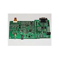
APMOTOR56F8000E
Description
KIT DEMO MOTOR CTRL SYSTEM
Manufacturer
Freescale Semiconductor
Type
Motor / Motion Controllers & Driversr
Datasheets
1.CWH-UTP-ONCE-HE.pdf
(2 pages)
2.APMOTOR56F8000E.pdf
(124 pages)
3.APMOTOR56F8000E.pdf
(2 pages)
Specifications of APMOTOR56F8000E
Accessory Type
Motor Controller
Input Voltage
9 V
Interface Type
RS-232
Product
Power Management Modules
For Use With/related Products
DEMO56F8013, DEMO56F8013-E
Lead Free Status / RoHS Status
Lead free / RoHS Compliant


The power modes provide additional means to disable clock domains, configure the voltage regulator, and
configure clock generation to manage power utilization, as shown in
modes provide means of enabling/disabling the peripheral and/or core clocking as a group. Stop disable
controls are provided for selected peripherals in the control register so that these peripheral clocks can
optionally continue to operate in Stop mode and generate interrupts which will return the part from Stop
to Run mode. Standby mode provides normal operation but at very low speed and power utilization. It is
possible to invoke Stop or Wait mode while in Standby mode for even greater levels of power reduction.
A 200 kHz clock external clock can optionally be used in Standby mode to produce the required Standby
100 kHz system bus rate. Power-down mode, which selects the ROSC clock source but shuts it off, fully
disables the part and minimizes its power utilization but is only recoverable via reset.
When the PLL is not selected and the system bus is operating at around 100 kHz, the large regulator can
78
Wait
Stop
Standby
Power-Down
Mode
Table 6-3 Clock Operation in Power-Down Modes (Continued)
Core and memory
clocks disabled
Master clock generation in the OCCS
remains operational, but the SIM disables
the generation of system and peripheral
clocks.
The OCCS generates the 2x System Clock
at a reduced frequency (200 kHz). The PLL
and high speed peripheral clocks are
disabled and the high-speed peripheral
option is not available. System and
peripheral clocks operate at 100 kHz.
Master clock generation in the OCCS is
completely shut down. All system and
peripheral clocks are disabled.
Core Clocks
56F8014 Technical Data, Rev. 11
Peripheral clocks
enabled
Peripheral Clocks
Core executes WAIT instruction to enter this
mode.
Typically used for power-conscious applications.
Possible recoveries from Wait mode to Run
mode are:
1. Any interrupt
2. Executing a Debug mode entry command
during the 56800E core JTAG interface
2. Any reset (POR, external, software, COP)
Core executes STOP instruction to enter this
mode. Possible recoveries from Stop mode to
Run mode are:
1. Interrupt from Timer channels that have been
configured to operate in Stop mode (TCx_SD)
2. Interrupt for SCI configured to operate in Stop
mode (SCI_SD)
3. Low-voltage interrupt
4. Executing a Debug mode entry command
using the 56800E core JTAG interface
5. Any reset (POR, external, software, COP)
The user configures the OCCS and SIM to select
the relaxation oscillator clock source (PRECS),
shut down the PLL (PLLPD), put the relaxation
oscillator in Standby mode (ROSB), and put the
large regulator in Standby (LRSTDBY). The part
is fully operational, but operating at a minimum
frequency and power configuration. Recovery
requires reversing the sequence used to enter
this mode (allowing for PLL lock time).
The user configures the OCCS and SIM to enter
Standby mode as shown in the previous
description, followed by powering down the
oscillator (ROPD). The only possible recoveries
from this mode are:
1. External reset
2. Power-on reset
Table
Description
6-3. Run, Wait, and Stop
Freescale Semiconductor
Related parts for APMOTOR56F8000E
Image
Part Number
Description
Manufacturer
Datasheet
Request
R

Part Number:
Description:
Manufacturer:
Freescale Semiconductor, Inc
Datasheet:
Part Number:
Description:
Manufacturer:
Freescale Semiconductor, Inc
Datasheet:
Part Number:
Description:
Manufacturer:
Freescale Semiconductor, Inc
Datasheet:
Part Number:
Description:
Manufacturer:
Freescale Semiconductor, Inc
Datasheet:
Part Number:
Description:
Manufacturer:
Freescale Semiconductor, Inc
Datasheet:
Part Number:
Description:
Manufacturer:
Freescale Semiconductor, Inc
Datasheet:
Part Number:
Description:
Manufacturer:
Freescale Semiconductor, Inc
Datasheet:
Part Number:
Description:
Manufacturer:
Freescale Semiconductor, Inc
Datasheet:
Part Number:
Description:
Manufacturer:
Freescale Semiconductor, Inc
Datasheet:
Part Number:
Description:
Manufacturer:
Freescale Semiconductor, Inc
Datasheet:
Part Number:
Description:
Manufacturer:
Freescale Semiconductor, Inc
Datasheet:
Part Number:
Description:
Manufacturer:
Freescale Semiconductor, Inc
Datasheet:
Part Number:
Description:
Manufacturer:
Freescale Semiconductor, Inc
Datasheet:
Part Number:
Description:
Manufacturer:
Freescale Semiconductor, Inc
Datasheet:
Part Number:
Description:
Manufacturer:
Freescale Semiconductor, Inc
Datasheet: