APMOTOR56F8000E Freescale Semiconductor, APMOTOR56F8000E Datasheet - Page 31
APMOTOR56F8000E
Manufacturer Part Number
APMOTOR56F8000E
Description
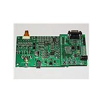
KIT DEMO MOTOR CTRL SYSTEM
Manufacturer
Freescale Semiconductor
Type
Motor / Motion Controllers & Driversr
Datasheets
1.CWH-UTP-ONCE-HE.pdf
(2 pages)
2.APMOTOR56F8000E.pdf
(124 pages)
3.APMOTOR56F8000E.pdf
(2 pages)
Specifications of APMOTOR56F8000E
Accessory Type
Motor Controller
Input Voltage
9 V
Interface Type
RS-232
Product
Power Management Modules
For Use With/related Products
DEMO56F8013, DEMO56F8013-E
Lead Free Status / RoHS Status
Lead free / RoHS Compliant


4.3 Program Map
The Program Memory map is shown in
Freescale Semiconductor
1. Two words are allocated for each entry in the vector table. This does not allow the full address range to be referenced
2. If the VBA is set to the reset value, the first two locations of the vector table will overlay the chip reset addresses.
Timer
Timer
ADC
ADC
ADC
PWM
PWM
SWILP
Peripheral
from the vector table, providing only 19 bits of address.
40
41
42
45
38
39
43
44
Number
Vector
Table 4-2 Interrupt Vector Table Contents
1. All addresses are 16-bit Word addresses.
2. This RAM is shared with Data space starting at address X: $00 0000;
P: $FF FFFF
P: $00 8800
P: $00 87FF
P: $00 8000
P: $00 7FFF
P: $00 2000
P: $00 1FFF
P: $00 0000
Begin/End Address
see
0-2
0-2
0-2
0-2
0-2
-1
0-2
0-2
Priority
Level
Figure
Table 4-3 Program Memory Map
4-1.
P:$4C
P:$4E
P:$50
P:$52
P:$54
P:$56
P:$58
P:$5A
Vector Base
Address +
56F8014 Technical Data, Rev. 11
Table
RESERVED
On-Chip RAM
4KB
RESERVED
Internal Program Flash
16KB
Cop Reset Address = $00 0002
Boot Location = $00 0000
4-3.
ADCA Conversion Complete
ADCB Conversion Complete
ADC Zero Crossing or Limit Error
Reload PWM
Timer Channel 2
Timer Channel 3
PWM Fault
SW Interrupt Low Priority
Memory Allocation
2
Interrupt Function
1
1
(Continued)
Program Map
31
Related parts for APMOTOR56F8000E
Image
Part Number
Description
Manufacturer
Datasheet
Request
R

Part Number:
Description:
Manufacturer:
Freescale Semiconductor, Inc
Datasheet:
Part Number:
Description:
Manufacturer:
Freescale Semiconductor, Inc
Datasheet:
Part Number:
Description:
Manufacturer:
Freescale Semiconductor, Inc
Datasheet:
Part Number:
Description:
Manufacturer:
Freescale Semiconductor, Inc
Datasheet:
Part Number:
Description:
Manufacturer:
Freescale Semiconductor, Inc
Datasheet:
Part Number:
Description:
Manufacturer:
Freescale Semiconductor, Inc
Datasheet:
Part Number:
Description:
Manufacturer:
Freescale Semiconductor, Inc
Datasheet:
Part Number:
Description:
Manufacturer:
Freescale Semiconductor, Inc
Datasheet:
Part Number:
Description:
Manufacturer:
Freescale Semiconductor, Inc
Datasheet:
Part Number:
Description:
Manufacturer:
Freescale Semiconductor, Inc
Datasheet:
Part Number:
Description:
Manufacturer:
Freescale Semiconductor, Inc
Datasheet:
Part Number:
Description:
Manufacturer:
Freescale Semiconductor, Inc
Datasheet:
Part Number:
Description:
Manufacturer:
Freescale Semiconductor, Inc
Datasheet:
Part Number:
Description:
Manufacturer:
Freescale Semiconductor, Inc
Datasheet:
Part Number:
Description:
Manufacturer:
Freescale Semiconductor, Inc
Datasheet: