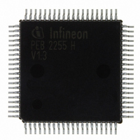
PEB2255H-V13 Infineon Technologies, PEB2255H-V13 Datasheet - Page 151

PEB2255H-V13
Manufacturer Part Number
PEB2255H-V13
Description
IC INTERFACE LINE 80-MQFP
Manufacturer
Infineon Technologies
Datasheet
1.PEB2255H-V13.pdf
(374 pages)
Specifications of PEB2255H-V13
Applications
*
Interface
*
Voltage - Supply
*
Package / Case
80-SQFP
Mounting Type
Surface Mount
Lead Free Status / RoHS Status
Lead free / RoHS Compliant
Other names
PEB2255H-V13
PEB2255H-V13IN
PEB2255H-V13IN
Available stocks
Company
Part Number
Manufacturer
Quantity
Price
Company:
Part Number:
PEB2255H-V13
Manufacturer:
Infineon Technologies
Quantity:
10 000
- Current page: 151 of 374
- Download datasheet (6Mb)
5.5.6
For support of common T1 applications, clear channels can be specified via the 3-byte
register bank CCB1 … CCB3. In this mode the contents of selected transmit time slots
are not overwritten by internally or externally sourced bit-robbing and zero code
suppression (B7 stuffing) information. Remote alarm signaling, however, overwrites
cleared channels.
5.5.7
The FALC
(00001) and loop-down/deactivate (001) pattern according to ANSI T1. 403 with bit error
rates as high as 1/100. Framed or unframed in-band loop code is selected by
LCR1.FLLB. Replacing the in-band loop codes with transmit data is done by FMR5.XLD/
XLU.
The FALC
up - and down pattern (LCR1.LLBP = 1). The loop up and loop down pattern is individual
programmable from 2 to 8 bit in length (LCR1.LAC1/0 and LCR1.LDC1/0). Programming
of loop codes is done in registers LCR2 and LCR3.
Status and interrupt-status bits inform the user whether a loop-up or loop-down code was
detected.
5.5.8
The transparent modes are useful for loopbacks or for routing data unchanged through
the FALC
In receive direction, transparency for ternary or dual/single rail unipolar data is achieved
if the receiver is in the synchronous state and FMR5.RTF has been selected. All bits in
F-bit position of the incoming multiframe are forwarded to RDO and inserted in the FS/
DL time slot or in the F-bit position. In asynchronous state the received data may be
transparently switched through if bit FMR2.DAIS is set. Setting of bit LOOP.RTM
disconnects control of the elastic buffer from the receiver. The elastic buffer is now in a
“free running” mode without any possibility to update the time slot assignment to a new
frame position in case of re-synchronization of the receiver. Together with FMR2.DAIS
this function may be used to realize undisturbed transparent reception.
Setting bit FMR4.TM switches the FALC
In transmit direction bit 8 of the FS/DL time slot from the system highway (XDI) is inserted
in the F-bit position of the outgoing frame. For complete transparency the internal
signaling controller, IDLE code generation, AIS/RA alarm generation, single channel and
payload loop back has to be disabled and “Clear Channels” have to be defined via
registers CCB1 3.
Data Sheet
®
®
®
-LH.
Clear Channel Capability
In-Band Loop Generation and Detection
-LH also offers the ability generating and detecting of a flexible in-band loop
Transparent Mode
-LH generates and detects a framed or unframed in-band loop-up/activate
®
-LH in transmit transparent mode:
151
Functional Description T1/J1
FALC-LH V1.3
PEB 2255
2000-07
Related parts for PEB2255H-V13
Image
Part Number
Description
Manufacturer
Datasheet
Request
R

Part Number:
Description:
E1/t1/j1 Framer And Line Interface Component For Long And Short Haul Applications
Manufacturer:
Infineon Technologies Corporation
Datasheet:

Part Number:
Description:
Manufacturer:
Infineon Technologies AG
Datasheet:

Part Number:
Description:
Manufacturer:
Infineon Technologies AG
Datasheet:

Part Number:
Description:
Manufacturer:
Infineon Technologies AG
Datasheet:

Part Number:
Description:
Manufacturer:
Infineon Technologies AG
Datasheet:

Part Number:
Description:
Manufacturer:
Infineon Technologies AG
Datasheet:

Part Number:
Description:
Manufacturer:
Infineon Technologies AG
Datasheet:

Part Number:
Description:
Manufacturer:
Infineon Technologies AG
Datasheet:

Part Number:
Description:
16-bit microcontroller with 2x2 KByte RAM
Manufacturer:
Infineon Technologies AG
Datasheet:

Part Number:
Description:
NPN silicon RF transistor
Manufacturer:
Infineon Technologies AG
Datasheet:

Part Number:
Description:
NPN silicon RF transistor
Manufacturer:
Infineon Technologies AG
Datasheet:

Part Number:
Description:
NPN silicon RF transistor
Manufacturer:
Infineon Technologies AG
Datasheet:

Part Number:
Description:
NPN silicon RF transistor
Manufacturer:
Infineon Technologies AG
Datasheet:

Part Number:
Description:
Si-MMIC-amplifier in SIEGET 25-technologie
Manufacturer:
Infineon Technologies AG
Datasheet:

Part Number:
Description:
IGBT Power Module
Manufacturer:
Infineon Technologies AG
Datasheet:


