R8A77850ADBGV#RD0Z Renesas Electronics America, R8A77850ADBGV#RD0Z Datasheet - Page 482
R8A77850ADBGV#RD0Z
Manufacturer Part Number
R8A77850ADBGV#RD0Z
Description
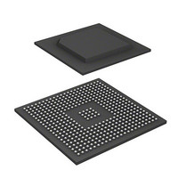
IC SUPERH MPU ROMLESS 436-BGA
Manufacturer
Renesas Electronics America
Series
SuperH® SH7780r
Datasheet
1.R8A77850AADBGV.pdf
(1694 pages)
Specifications of R8A77850ADBGV#RD0Z
Core Processor
SH-4A
Core Size
32-Bit
Speed
600MHz
Connectivity
Audio Codec, MMC, Serial Sound, SCI, SIO, SPI, SSI
Peripherals
DMA, POR, WDT
Number Of I /o
108
Program Memory Type
ROMless
Ram Size
8K x 8
Voltage - Supply (vcc/vdd)
1 V ~ 1.2 V
Oscillator Type
External
Operating Temperature
-40°C ~ 85°C
Package / Case
436-BGA
Lead Free Status / RoHS Status
Lead free / RoHS Compliant
Eeprom Size
-
Program Memory Size
-
Data Converters
-
Available stocks
Company
Part Number
Manufacturer
Quantity
Price

Part Number:
R8A77850ADBGV#RD0ZR8A77850ADBGV
Manufacturer:
Renesas Electronics America
Quantity:
10 000


11. Local Bus State Controller (LBSC)
11.5.10 Master Mode
The processor in master mode holds the bus itself until it receives a bus request.
On receiving an assertion (low level) of the bus request signal (BREQ) from the outside, the
master mode processor releases the bus and asserts (drives low) the bus use permission signal
(BACK) as soon as the currently executing bus cycle ends. On receiving the BREQ negation (high
level) indicating that the slave has released the bus, the processor negates (drives high) the BACK
signal and resumes use of the bus.
When the bus is released, all bus control output signals and input/output signals related to bus
interface enters a high-impedance state, except for BACK for bus arbitration and DACK0 to
DACK3 for controlling DMA transfer.
The actual bus release sequence is as follows.
First, the bus use permission signal is asserted in synchronization with the rising edge of the clock.
The address bus and data bus are put in a high-impedance state in synchronous with the rising
edge of the clock next to the BACK assertion. At the same time, the bus control signals (BS, CSn,
WEn, RD, R/W, CE2A, and CE2B) enters a high-impedance state. These bus control signals are
negated no later than one cycle before entering high-impedance. Bus request signal sampling is
performed on the rising edge of the clock.
The sequence for re-acquiring the bus from the slave is as follows.
As soon as BREQ negation is detected on the rising edge of the clock, BACK is negated and bus
control signal driving is started. Driving of the address bus and data bus starts at the next rising
edge of an in-phase clock. The bus control signals are asserted and the bus cycle is actually
started, at the earliest, at the clock rising edge at which the address and data signals are driven.
In order to reacquire the bus and start execution of bus access, the BREQ signal must be negated
for at least two cycles.
Rev.1.00 Jan. 10, 2008 Page 450 of 1658
REJ09B0261-0100
Related parts for R8A77850ADBGV#RD0Z
Image
Part Number
Description
Manufacturer
Datasheet
Request
R

Part Number:
Description:
KIT STARTER FOR M16C/29
Manufacturer:
Renesas Electronics America
Datasheet:

Part Number:
Description:
KIT STARTER FOR R8C/2D
Manufacturer:
Renesas Electronics America
Datasheet:

Part Number:
Description:
R0K33062P STARTER KIT
Manufacturer:
Renesas Electronics America
Datasheet:

Part Number:
Description:
KIT STARTER FOR R8C/23 E8A
Manufacturer:
Renesas Electronics America
Datasheet:

Part Number:
Description:
KIT STARTER FOR R8C/25
Manufacturer:
Renesas Electronics America
Datasheet:

Part Number:
Description:
KIT STARTER H8S2456 SHARPE DSPLY
Manufacturer:
Renesas Electronics America
Datasheet:

Part Number:
Description:
KIT STARTER FOR R8C38C
Manufacturer:
Renesas Electronics America
Datasheet:

Part Number:
Description:
KIT STARTER FOR R8C35C
Manufacturer:
Renesas Electronics America
Datasheet:

Part Number:
Description:
KIT STARTER FOR R8CL3AC+LCD APPS
Manufacturer:
Renesas Electronics America
Datasheet:
Part Number:
Description:
KIT STARTER FOR RX610
Manufacturer:
Renesas Electronics America
Datasheet:

Part Number:
Description:
KIT STARTER FOR R32C/118
Manufacturer:
Renesas Electronics America
Datasheet:

Part Number:
Description:
KIT DEV RSK-R8C/26-29
Manufacturer:
Renesas Electronics America
Datasheet:

Part Number:
Description:
KIT STARTER FOR SH7124
Manufacturer:
Renesas Electronics America
Datasheet:

Part Number:
Description:
KIT STARTER FOR H8SX/1622
Manufacturer:
Renesas Electronics America
Datasheet:

Part Number:
Description:
KIT DEV FOR SH7203
Manufacturer:
Renesas Electronics America
Datasheet: