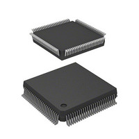
HD6417034AFI20 Renesas Electronics America, HD6417034AFI20 Datasheet - Page 75

HD6417034AFI20
Manufacturer Part Number
HD6417034AFI20
Description
IC SUPERH MPU ROMLESS 112QFP
Manufacturer
Renesas Electronics America
Series
SuperH® SH7030r
Datasheet
1.HD6417034AFI20.pdf
(689 pages)
Specifications of HD6417034AFI20
Core Processor
SH-1
Core Size
32-Bit
Speed
20MHz
Connectivity
EBI/EMI, SCI
Peripherals
DMA, POR, PWM, WDT
Number Of I /o
32
Program Memory Type
ROMless
Ram Size
4K x 8
Voltage - Supply (vcc/vdd)
4.5 V ~ 5.5 V
Data Converters
A/D 8x10b
Oscillator Type
Internal
Operating Temperature
-20°C ~ 75°C
Package / Case
112-QFP
Lead Free Status / RoHS Status
Contains lead / RoHS non-compliant
Eeprom Size
-
Program Memory Size
-
Available stocks
Company
Part Number
Manufacturer
Quantity
Price
Company:
Part Number:
HD6417034AFI20
Manufacturer:
Renesas Electronics America
Quantity:
10 000
Company:
Part Number:
HD6417034AFI20V
Manufacturer:
Renesas Electronics America
Quantity:
10 000
- Current page: 75 of 689
- Download datasheet (5Mb)
Section 2 CPU
Reset State: In the reset state the CPU is reset. This occurs when the RES pin level goes low.
When the NMI pin is high, the result is a power-on reset; when it is low, a manual reset will occur.
When turning on the power, be sure to carry out a power-on reset.
In a power-on reset, all CPU internal states and on-chip supporting module registers are initialized.
In a manual reset, all CPU internal states and on-chip supporting module registers, with the
exception of the bus state controller (BSC) and pin function controller (PFC), are initialized. In a
manual reset, the BSC is not initialized, so refresh operations will continue.
Exception Handling State: Exception handling is a transient state that occurs when the CPU’s
processing state flow is altered by exception handling sources such as resets or interrupts.
In a reset, the initial values of the program counter PC (execution start address) and stack pointer
SP are fetched from the exception vector table and stored; the CPU then branches to the execution
start address and execution of the program begins.
For an interrupt, the stack pointer (SP) is accessed and the program counter (PC) and status
register (SR) are saved to the stack area. The exception handling routine start address is fetched
from the exception vector table; the CPU then branches to that address and the program starts
executing, thereby entering the program execution state.
Program Execution State: In the program execution state, the CPU sequentially executes the
program.
Power-Down State: In the power-down state, CPU operation halts and power consumption
decreases. The SLEEP instruction places the CPU in the power-down state. This state has two
modes: sleep mode and standby mode.
Bus-Released State: In the bus-released state, the CPU releases the bus to the device that has
requested it.
Rev. 7.00 Jan 31, 2006 page 47 of 658
REJ09B0272-0700
Related parts for HD6417034AFI20
Image
Part Number
Description
Manufacturer
Datasheet
Request
R

Part Number:
Description:
KIT STARTER FOR M16C/29
Manufacturer:
Renesas Electronics America
Datasheet:

Part Number:
Description:
KIT STARTER FOR R8C/2D
Manufacturer:
Renesas Electronics America
Datasheet:

Part Number:
Description:
R0K33062P STARTER KIT
Manufacturer:
Renesas Electronics America
Datasheet:

Part Number:
Description:
KIT STARTER FOR R8C/23 E8A
Manufacturer:
Renesas Electronics America
Datasheet:

Part Number:
Description:
KIT STARTER FOR R8C/25
Manufacturer:
Renesas Electronics America
Datasheet:

Part Number:
Description:
KIT STARTER H8S2456 SHARPE DSPLY
Manufacturer:
Renesas Electronics America
Datasheet:

Part Number:
Description:
KIT STARTER FOR R8C38C
Manufacturer:
Renesas Electronics America
Datasheet:

Part Number:
Description:
KIT STARTER FOR R8C35C
Manufacturer:
Renesas Electronics America
Datasheet:

Part Number:
Description:
KIT STARTER FOR R8CL3AC+LCD APPS
Manufacturer:
Renesas Electronics America
Datasheet:

Part Number:
Description:
KIT STARTER FOR RX610
Manufacturer:
Renesas Electronics America
Datasheet:

Part Number:
Description:
KIT STARTER FOR R32C/118
Manufacturer:
Renesas Electronics America
Datasheet:

Part Number:
Description:
KIT DEV RSK-R8C/26-29
Manufacturer:
Renesas Electronics America
Datasheet:

Part Number:
Description:
KIT STARTER FOR SH7124
Manufacturer:
Renesas Electronics America
Datasheet:

Part Number:
Description:
KIT STARTER FOR H8SX/1622
Manufacturer:
Renesas Electronics America
Datasheet:

Part Number:
Description:
KIT DEV FOR SH7203
Manufacturer:
Renesas Electronics America
Datasheet:


