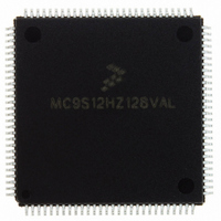
MC9S12HZ128VAL Freescale Semiconductor, MC9S12HZ128VAL Datasheet - Page 272

MC9S12HZ128VAL
Manufacturer Part Number
MC9S12HZ128VAL
Description
IC MCU 16BIT 2K FLASH 112-LQFP
Manufacturer
Freescale Semiconductor
Series
HCS12r
Datasheet
1.MC9S12HZ128CAL.pdf
(692 pages)
Specifications of MC9S12HZ128VAL
Core Processor
HCS12
Core Size
16-Bit
Speed
25MHz
Connectivity
CAN, EBI/EMI, I²C, SCI, SPI
Peripherals
LCD, Motor control PWM, POR, PWM, WDT
Number Of I /o
85
Program Memory Size
128KB (128K x 8)
Program Memory Type
FLASH
Eeprom Size
2K x 8
Ram Size
6K x 8
Voltage - Supply (vcc/vdd)
2.35 V ~ 5.5 V
Data Converters
A/D 16x10b
Oscillator Type
Internal
Operating Temperature
-40°C ~ 105°C
Package / Case
112-LQFP
Processor Series
S12H
Core
HCS12
Data Bus Width
16 bit
Data Ram Size
6 KB
Interface Type
I2C/SCI/SPI
Maximum Clock Frequency
50 MHz
Number Of Programmable I/os
85
Number Of Timers
8
Maximum Operating Temperature
+ 105 C
Mounting Style
SMD/SMT
3rd Party Development Tools
EWHCS12
Minimum Operating Temperature
- 40 C
On-chip Adc
16-ch x 10-bit
Lead Free Status / RoHS Status
Lead free / RoHS Compliant
Available stocks
Company
Part Number
Manufacturer
Quantity
Price
Company:
Part Number:
MC9S12HZ128VAL
Manufacturer:
Freescale Semiconductor
Quantity:
10 000
Part Number:
MC9S12HZ128VAL
Manufacturer:
FREESCALE
Quantity:
20 000
- Current page: 272 of 692
- Download datasheet (4Mb)
Chapter 9 Motor Controller (MC10B8CV1)
9.4.1.1.1
PWM channel pairs x and x + 1 operate in dual full H-bridge mode if both channels have been enabled
(MCAM[1:0]=01, 10, or 11) and both of the corresponding output mode bits MCOM[1:0] in both PWM
channel control registers are set.
A typical configuration in dual full H-bridge mode is shown in
PWM output signal on either MnC0P or MnC0M. If MnC0P drives the PWM signal, MnC0M will be
output either high or low depending on the RECIRC bit. If MnC0M drives the PWM signal, MnC0P will
be an output high or low. PWM channel x + 1 drives the PWM output signal on either MnC1P or MnC1M.
If MnC1P drives the PWM signal, MnC1M will be an output high or low. If MnC1M drives the PWM
signal, MnC1P will be an output high or low. This results in motor recirculation currents on the high side
drivers (RECIRC = 0) while the PWM signal is at a logic high level, or motor recirculation currents on the
low side drivers (RECIRC = 1) while the PWM signal is at a logic low level. The pin driving the PWM
signal is determined by the S (sign) bit in the corresponding duty cycle register and the state of the
RECIRC bit. The value of the PWM duty cycle is determined by the value of the D[10:0] or D[8:2] bits
respectively in the duty cycle register depending on the state of the FAST bit.
272
Pair Number
Table 9-10. Corresponding Registers and Pin Names for Each PWM Channel Pair (continued)
Channel
PWM
1
2
3
Dual Full H-Bridge Mode (MCOM = 11)
Channel Control
Register
MCMC2
MCMC3
MCMC4
MCMC5
MCMC6
MCMC7
PWM
MC9S12HZ256 Data Sheet, Rev. 2.05
Duty Cycle
Register
MCDC2
MCDC3
MCDC4
MCDC5
MCDC6
MCDC7
Figure
PWM Channel 2
PWM Channel 3
PWM Channel 4
PWM Channel 5
PWM Channel 6
PWM Channel 7
Channel
Number
9-10. PWM channel x drives the
Freescale Semiconductor
M1C0M
M1C1M
M2C0M
M2C1M
M3C0M
M3C1M
Names
M1C0P
M1C1P
M2C0P
M2C1P
M3C0P
M3C1P
Pin
Related parts for MC9S12HZ128VAL
Image
Part Number
Description
Manufacturer
Datasheet
Request
R
Part Number:
Description:
Manufacturer:
Freescale Semiconductor, Inc
Datasheet:
Part Number:
Description:
Manufacturer:
Freescale Semiconductor, Inc
Datasheet:
Part Number:
Description:
Manufacturer:
Freescale Semiconductor, Inc
Datasheet:
Part Number:
Description:
Manufacturer:
Freescale Semiconductor, Inc
Datasheet:
Part Number:
Description:
Manufacturer:
Freescale Semiconductor, Inc
Datasheet:
Part Number:
Description:
Manufacturer:
Freescale Semiconductor, Inc
Datasheet:
Part Number:
Description:
Manufacturer:
Freescale Semiconductor, Inc
Datasheet:
Part Number:
Description:
Manufacturer:
Freescale Semiconductor, Inc
Datasheet:
Part Number:
Description:
Manufacturer:
Freescale Semiconductor, Inc
Datasheet:
Part Number:
Description:
Manufacturer:
Freescale Semiconductor, Inc
Datasheet:
Part Number:
Description:
Manufacturer:
Freescale Semiconductor, Inc
Datasheet:
Part Number:
Description:
Manufacturer:
Freescale Semiconductor, Inc
Datasheet:
Part Number:
Description:
Manufacturer:
Freescale Semiconductor, Inc
Datasheet:
Part Number:
Description:
Manufacturer:
Freescale Semiconductor, Inc
Datasheet:
Part Number:
Description:
Manufacturer:
Freescale Semiconductor, Inc
Datasheet:


