EVAL-ADUC832QSZ Analog Devices Inc, EVAL-ADUC832QSZ Datasheet - Page 51
EVAL-ADUC832QSZ
Manufacturer Part Number
EVAL-ADUC832QSZ
Description
KIT DEV FOR ADUC832 QUICK START
Manufacturer
Analog Devices Inc
Series
QuickStart™ Kitr
Type
MCUr
Specifications of EVAL-ADUC832QSZ
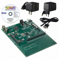
Contents
Evaluation Board, Cable, Power Supply, Software and Documentation
Lead Free Status / RoHS Status
Lead free / RoHS Compliant
For Use With/related Products
ADuC832
Lead Free Status / RoHS Status
Compliant, Lead free / RoHS Compliant
Other names
EVAL-ADUC832QS
EVAL-ADUC832QS
EVAL-ADUC832QS


Timers/Counters
The ADuC832 has three 16-bit Timer/Counters: Timer 0,
Timer 1, and Timer 2. The Timer/Counter hardware has been
included on-chip to relieve the processor core of the overhead
inherent in implementing Timer/Counter functionality in soft-
ware. Each Timer/Counter consists of two 8-bit registers THx
and TLx (x = 0, 1 and 2). All three can be configured to operate
either as timers or event counters.
In Timer function, the TLx register is incremented every machine
cycle. Thus, one can think of it as counting machine cycles. Since
a machine cycle consists of 12 core clock periods, the maximum
count rate is 1/12 the core clock frequency.
User configuration and control of all Timer operating modes is achieved via three SFRs:
TMOD, TCON
T2CON
TMOD
SFR Address
Power-On Default Value
Bit Addressable
Bit
7
6
5
4
3
2
1
0
REV. 0
Name
Gate
C/T
M1
M0
Gate
C/T
M1
M0
Control and configuration for Timers 0 and 1.
Control and configuration for Timer 2.
Timer/Counter 0 and 1 Mode Register
89H
00H
No
Description
Timer 1 Gating Control.
Set by software to enable Timer/Counter 1 only while INT1 pin is high and TR1 control bit is set.
Cleared by software to enable Timer 1 whenever TR1 control bit is set.
Timer 1 Timer or Counter Select Bit.
Set by software to select counter operation (input from T1 pin).
Cleared by software to select timer operation (input from internal system clock).
Timer 1 Mode Select Bit 1 (Used with M0 Bit).
Timer 1 Mode Select Bit 0.
M1
0
0
1
1
Timer 0 Gating Control.
Set by software to enable timer/counter 0 only while INT0 pin is high and TR0 control bit is set.
Cleared by software to enable Timer 0 whenever TR0 control bit is set.
Timer 0 Timer or Counter Select Bit.
Set by software to select counter operation (input from T0 pin).
Cleared by software to select timer operation (input from internal system clock).
Timer 0 Mode Select Bit 1.
Timer 0 Mode Select Bit 0.
M1
0
0
1
1
Table XX. TMOD SFR Bit Designations
M0
0
1
0
1
M0
0
1
0
1
TH1 operates as an 8-bit timer/counter. TL1 serves as 5-bit prescaler.
16-Bit Timer/Counter. TH1 and TL1 are cascaded; there is no prescaler.
8-Bit Auto-Reload Timer/Counter. TH1 holds a value that is to be
reloaded into TL1 each time it overflows.
Timer/Counter 1 Stopped.
TH0 operates as an 8-bit timer/counter. TL0 serves as a 5-bit prescaler.
16-Bit Timer/Counter. TH0 and TL0 are cascaded; there is no prescaler.
8-Bit Auto-Reload Timer/Counter. TH0 holds a value that is to
be reloaded into TL0 each time it overflows.
TL0 is an 8-bit timer/counter controlled by the standard timer 0 control bits.
TH0 is an 8-bit timer only, controlled by Timer 1 control bits.
–51–
In Counter function, the TLx register is incremented by a 1-to-0
transition at its corresponding external input pin, T0, T1, or T2.
In this function, the external input is sampled during S5P2 of
every machine cycle. When the samples show a high in one
cycle and a low in the next cycle, the count is incremented. The
new count value appears in the register during S3P1 of the cycle
following the one in which the transition was detected. Since it
takes two machine cycles (24 core clock periods) to recognize a
1-to-0 transition, the maximum count rate is 1/24 the core clock
frequency. There are no restrictions on the duty cycle of the
external input signal, but to ensure that a given level is sampled
at least once before it changes, it must be held for a minimum of
one full machine cycle.
ADuC832
Related parts for EVAL-ADUC832QSZ
Image
Part Number
Description
Manufacturer
Datasheet
Request
R


Part Number:
Description:
BOARD EVAL FOR SI270X-A
Manufacturer:
Silicon Laboratories Inc
Datasheet:

Part Number:
Description:
BUCK CONV REF DESIGN KIT IP1201
Manufacturer:
International Rectifier
Datasheet:
Part Number:
Description:
BOARD DEMO SYNC DUAL BUCK CNVTER
Manufacturer:
International Rectifier
Datasheet:
Part Number:
Description:
BOARD DEMO SYNC BUCK CONVETER
Manufacturer:
International Rectifier
Datasheet:

Part Number:
Description:
EVALBOARD/EB Omnidirectional microphone - Analog
Manufacturer:
Analog Devices
Datasheet:
Part Number:
Description:
EVALBOARD/EB Omnidirectional microphone - Analog
Manufacturer:
Analog Devices
Datasheet:


Part Number:
Description:
BOARD EVAL LED DRIVER LT3756
Manufacturer:
Linear Technology
Datasheet:

Part Number:
Description:
BOARD EVAL FOR AD7741/7742
Manufacturer:
Analog Devices Inc
Datasheet:

Part Number:
Description:
±1.7g Dual-Axis IMEMS Accelerometer Evaluation Board
Manufacturer:
Analog Devices Inc
Datasheet:

Part Number:
Description:
IC MULTIPLIER ANALOG 8-SOIC T/R
Manufacturer:
Analog Devices Inc
Datasheet:

Part Number:
Description:
IC ANALOG MULTIPLIER 8-DIP
Manufacturer:
Analog Devices Inc
Datasheet:
Part Number:
Description:
IC ANALOG MULTIPLIER 8-SOIC
Manufacturer:
Analog Devices Inc
Datasheet:
Part Number:
Description:
IC ANALOG MULTIPLIER 8-DIP
Manufacturer:
Analog Devices Inc
Datasheet: