EVAL-ADUC832QSZ Analog Devices Inc, EVAL-ADUC832QSZ Datasheet - Page 25
EVAL-ADUC832QSZ
Manufacturer Part Number
EVAL-ADUC832QSZ
Description
KIT DEV FOR ADUC832 QUICK START
Manufacturer
Analog Devices Inc
Series
QuickStart™ Kitr
Type
MCUr
Specifications of EVAL-ADUC832QSZ
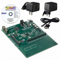
Contents
Evaluation Board, Cable, Power Supply, Software and Documentation
Lead Free Status / RoHS Status
Lead free / RoHS Compliant
For Use With/related Products
ADuC832
Lead Free Status / RoHS Status
Compliant, Lead free / RoHS Compliant
Other names
EVAL-ADUC832QS
EVAL-ADUC832QS
EVAL-ADUC832QS


The DMA logic operates from the ADC clock and uses pipelining
to perform the ADC conversions and access the external memory
at the same time. The time it takes to perform one ADC conver-
sion is called a DMA cycle. The actions performed by the logic
during a typical DMA cycle are shown in the following diagram.
From the previous diagram, it can be seen that during one DMA
cycle, the following actions are performed by the DMA logic:
1. An ADC conversion is performed on the channel whose ID
2. The 12-bit result and the channel ID of the conversion per-
3. The ID of the next channel to be converted is read from
For the previous example, the complete flow of events is shown
in Figure 16. Because the DMA logic uses pipelining, it takes
three cycles before the first correct result is written out.
Micro Operation during ADC DMA Mode
During ADC DMA mode, the MicroConverter core is free to
continue code execution, including general housekeeping and
communication tasks. However, note that MCU core accesses to
Ports 0 and 2 (which of course are being used by the DMA con-
troller) are gated “OFF” during ADC DMA mode of operation.
This means that even though the instruction that accesses the
external ports 0 or 2 will appear to execute, no data will be seen
at these external Ports as a result. Note that during DMA to the
internally contained XRAM, Ports 0 and 2 are available for use.
The only case in which the MCU will be able to access XRAM
during DMA is when the internal XRAM is enabled and the
section of RAM to which the DMA ADC results are being written
to lies in an external XRAM. Then the MCU will be able to
access the internal XRAM only. This is also the case for use of
the extended stack pointer.
The MicroConverter core can be configured with an interrupt to
be triggered by the DMA controller when it has finished filling
the requested block of RAM with ADC results, allowing the
service routine for this interrupt to postprocess data without any
real-time timing constraints.
REV. 0
was read during the previous cycle.
formed in the previous cycle is written to the external memory.
external memory.
CONVERT CHANNEL READ DURING PREVIOUS DMA CYCLE
PREVIOUS DMA CYCLE
CONVERTED DURING
WRITE ADC RESULT
Figure 16. DMA Cycle
DMA CYCLE
TO BE CONVERTED DURING
READ CHANNEL ID
NEXT DMA CYCLE
–25–
ADC Offset and Gain Calibration Coefficients
The ADuC832 has two ADC calibration coefficients, one for
offset calibration and one for gain calibration. Both the offset
and gain calibration coefficients are 14-bit words, and are each
stored in two registers located in the Special Function Register
(SFR) area. The offset calibration coefficient is divided into
ADCOFSH (six bits) and ADCOFSL (eight bits) and the gain
calibration coefficient is divided into ADCGAINH (six bits) and
ADCGAINL (eight bits).
The offset calibration coefficient compensates for dc offset errors
in both the ADC and the input signal. Increasing the offset
coefficient compensates for positive offset, and effectively pushes
the ADC transfer function down. Decreasing the offset coefficient
compensates for negative offset, and effectively pushes the ADC
transfer function up. The maximum offset that can be compensated
is typically ± 5% of V
with a 2.5 V reference.
Similarly, the gain calibration coefficient compensates for dc
gain errors in both the ADC and the input signal. Increasing
the gain coefficient compensates for a smaller analog input signal
range and scales the ADC transfer function up, effectively
increasing the slope of the transfer function. Decreasing the gain
coefficient compensates for a larger analog input signal range and
scales the ADC transfer function down, effectively decreasing
the slope of the transfer function. The maximum analog input
signal range for which the gain coefficient can compensate is
1.025
which equates to typically ± 2.5% of the reference voltage.
CALIBRATING THE ADC
There are two hardware calibration modes provided that can be
easily initiated by user software. The ADCCON3 SFR is used
to calibrate the ADC. Bit 1 (TYPICAL) and the CS3 to CS0
(ADCCON2) set up the calibration modes.
Device calibration can be initiated to compensate for significant
changes in operating conditions frequency, analog input range,
reference voltage, and supply voltages. In this calibration mode,
offset calibration uses internal AGND selected via ADCCON2
register bits CS3–CS0 (1011) and gain calibration uses internal
V
executed first, followed by gain calibration.
System calibration can be initiated to compensate for both inter-
nal and external system errors. To perform system calibration
using an external reference, tie system ground and reference to
any two of the six selectable inputs. Enable external reference
mode (ADCCON1.6). Select the channel connected to AGND
via CS3–CS0 and perform system offset calibration. Select the
channel connected to V
gain calibration.
The ADC should be configured to use settings for an ADCCLK
of divide by 16 and 4 acquisition clocks.
REF
selected by CS3–CS0 (1100). Offset calibration should be
V
REF
and the minimum input range is 0.975
REF
REF
, which equates to typically ± 125 mV
via CS3–CS0 and perform system
ADuC832
V
REF
,
Related parts for EVAL-ADUC832QSZ
Image
Part Number
Description
Manufacturer
Datasheet
Request
R


Part Number:
Description:
BOARD EVAL FOR SI270X-A
Manufacturer:
Silicon Laboratories Inc
Datasheet:

Part Number:
Description:
BUCK CONV REF DESIGN KIT IP1201
Manufacturer:
International Rectifier
Datasheet:
Part Number:
Description:
BOARD DEMO SYNC DUAL BUCK CNVTER
Manufacturer:
International Rectifier
Datasheet:
Part Number:
Description:
BOARD DEMO SYNC BUCK CONVETER
Manufacturer:
International Rectifier
Datasheet:

Part Number:
Description:
EVALBOARD/EB Omnidirectional microphone - Analog
Manufacturer:
Analog Devices
Datasheet:
Part Number:
Description:
EVALBOARD/EB Omnidirectional microphone - Analog
Manufacturer:
Analog Devices
Datasheet:


Part Number:
Description:
BOARD EVAL LED DRIVER LT3756
Manufacturer:
Linear Technology
Datasheet:

Part Number:
Description:
BOARD EVAL FOR AD7741/7742
Manufacturer:
Analog Devices Inc
Datasheet:

Part Number:
Description:
±1.7g Dual-Axis IMEMS Accelerometer Evaluation Board
Manufacturer:
Analog Devices Inc
Datasheet:

Part Number:
Description:
IC MULTIPLIER ANALOG 8-SOIC T/R
Manufacturer:
Analog Devices Inc
Datasheet:

Part Number:
Description:
IC ANALOG MULTIPLIER 8-DIP
Manufacturer:
Analog Devices Inc
Datasheet:
Part Number:
Description:
IC ANALOG MULTIPLIER 8-SOIC
Manufacturer:
Analog Devices Inc
Datasheet:
Part Number:
Description:
IC ANALOG MULTIPLIER 8-DIP
Manufacturer:
Analog Devices Inc
Datasheet: