MT46H8M32LFB5-6:A TR Micron Technology Inc, MT46H8M32LFB5-6:A TR Datasheet - Page 63
MT46H8M32LFB5-6:A TR
Manufacturer Part Number
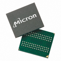
MT46H8M32LFB5-6:A TR
Description
IC DDR SDRAM 256MBIT 90VFBGA
Manufacturer
Micron Technology Inc
Type
DDR SDRAMr
Specifications of MT46H8M32LFB5-6:A TR
Format - Memory
RAM
Memory Type
Mobile DDR SDRAM
Memory Size
256M (8Mx32)
Speed
166MHz
Interface
Parallel
Voltage - Supply
1.7 V ~ 1.95 V
Operating Temperature
0°C ~ 70°C
Package / Case
90-VFBGA
Organization
8Mx32
Density
256Mb
Address Bus
14b
Access Time (max)
6.5/5ns
Maximum Clock Rate
166MHz
Operating Supply Voltage (typ)
1.8V
Package Type
VFBGA
Operating Temp Range
0C to 70C
Operating Supply Voltage (max)
1.95V
Operating Supply Voltage (min)
1.7V
Supply Current
120mA
Pin Count
90
Mounting
Surface Mount
Operating Temperature Classification
Commercial
Lead Free Status / RoHS Status
Lead free / RoHS Compliant
Other names
557-1280-2
MT46H8M32LFB5-6:A TR
MT46H8M32LFB5-6:A TR


Notes
PDF: 09005aef82091978 / Source: 09005aef8209195b
MT46H16M16LF__2.fm - Rev. H 6/08 EN
10. Enables on-chip refresh and address counters.
11. Fast command/address input slew rate ≥1 V/ns. Slow command/address input slew
12.
13. The maximum limit for this parameter is not a device limit. The device will operate
14. This is not a device limit. The device will operate with a negative value, but system
15. It is recommended that DQS be valid (HIGH or LOW) on or before the WRITE com-
2. All parameters assume proper device initialization.
3. Tests for AC timing, I
4. Outputs measured with equivalent load; transmission line delay is assumed to be very
5. Timing and I
6. All AC timings assume an input slew rate of 1V/ns.
7. V
8. The value of V
9. I
1. All voltages referenced to V
at nominal supply voltage levels, but the related specifications and device operation
are guaranteed for the full voltage range specified.
small:
but input timing is still referenced to V
The output timing reference voltage level is V
level on CK#.
track variations in the DC level of the same.
with minimum cycle time at CL = 3 for -6 and CL = 3 for -75 with the outputs open.
rate ≥0.5 V/ns. If the slew rate is less than 0.5 V/ns, timing must be derated:
additional 50ps per each 100 mV/ns reduction in slew rate from the 0.5 V/ns.
remains constant. If the slew rate exceeds 4.5 V/ns, functionality is uncertain.
t
tions. These parameters are not referenced to a specific voltage level but specify when
the device output is no longer driving (HZ) or begins driving (LZ).
with a greater value for this parameter, but system performance (bus turnaround) will
degrade accordingly.
performance (bus turnaround) will degrade accordingly.
mand. The case shown (DQS going from High-Z to logic LOW) applies when no
WRITEs were previously in progress on the bus. If a previous WRITE was in progress,
DQS could be HIGH during this time, depending on
I/O
I/O
DD
HZ and
One-half-drive strength
ID
Full-drive strength
is the magnitude of the difference between the input level on CK and the input
is dependent on output loading and cycle rates. Specified values are obtained
Z
Z
0
0
= 50
= 50
t
LZ transitions occur in the same access time windows as data valid transi-
DD
IX
tests may use a V
is expected to equal V
20pF
10pF
DD
, and electrical AC and DC characteristics may be conducted
63
SS
.
One-eighth-drive strength
I/O
I/O
IL
-to-V
Quarter-drive strength
Micron Technology, Inc., reserves the right to change products or specifications without notice.
256Mb: x16, x32 Mobile DDR SDRAM
Z
Z
DD
DD
0
0
IH
= 50
= 50
Q/2 of the transmitting device and must
Q/2 (or to the crossing point for CK/CK#).
swing of up to 1.5V in the test environment,
DD
Q/2.
5pF
2.5pF
t
DQSS.
©2005 Micron Technology, Inc. All rights reserved.
t
IS has an
t
IH
Notes
Related parts for MT46H8M32LFB5-6:A TR
Image
Part Number
Description
Manufacturer
Datasheet
Request
R

Part Number:
Description:
IC SDRAM 64MBIT 133MHZ 54TSOP
Manufacturer:
Micron Technology Inc
Datasheet:

Part Number:
Description:
IC SDRAM 64MBIT 5.5NS 86TSOP
Manufacturer:
Micron Technology Inc
Datasheet:
Part Number:
Description:
IC SDRAM 64MBIT 200MHZ 86TSOP
Manufacturer:
Micron Technology Inc
Datasheet:
Part Number:
Description:
IC SDRAM 64MBIT 133MHZ 54TSOP
Manufacturer:
Micron Technology Inc
Datasheet:
Part Number:
Description:
IC SDRAM 128MBIT 133MHZ 54TSOP
Manufacturer:
Micron Technology Inc
Datasheet:

Part Number:
Description:
IC SDRAM 256MBIT 133MHZ 90VFBGA
Manufacturer:
Micron Technology Inc
Datasheet:
Part Number:
Description:
IC SDRAM 128MBIT 133MHZ 54TSOP
Manufacturer:
Micron Technology Inc
Datasheet:
Part Number:
Description:
IC SDRAM 256MBIT 133MHZ 54TSOP
Manufacturer:
Micron Technology Inc
Datasheet:

Part Number:
Description:
IC DDR SDRAM 512MBIT 6NS 66TSOP
Manufacturer:
Micron Technology Inc
Datasheet:
Part Number:
Description:
IC SDRAM 128MBIT 167MHZ 86TSOP
Manufacturer:
Micron Technology Inc
Datasheet:
Part Number:
Description:
IC SDRAM 128MBIT 143MHZ 86TSOP
Manufacturer:
Micron Technology Inc
Datasheet:

Part Number:
Description:
SDRAM 256M-BIT 1.8V 54-PIN VFBGA
Manufacturer:
Micron Technology Inc
Datasheet:
Part Number:
Description:
IC SDRAM 128MBIT 143MHZ 86TSOP
Manufacturer:
Micron Technology Inc
Datasheet:

Part Number:
Description:
IC SDRAM 128MBIT 125MHZ 54VFBGA
Manufacturer:
Micron Technology Inc
Datasheet:
Part Number:
Description:
IC SDRAM 128MBIT 125MHZ 54VFBGA
Manufacturer:
Micron Technology Inc
Datasheet: