MCIMX53-START Freescale Semiconductor, MCIMX53-START Datasheet - Page 76
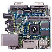
MCIMX53-START
Manufacturer Part Number
MCIMX53-START
Description
KIT DEVELOPMENT I.MX53
Manufacturer
Freescale Semiconductor
Series
i.MX53r
Type
MCUr
Datasheets
1.MCIMX53-START.pdf
(2 pages)
2.MCIMX53-START.pdf
(180 pages)
3.MCIMX53-START.pdf
(204 pages)
Specifications of MCIMX53-START
Contents
Board
Silicon Manufacturer
Freescale
Core Architecture
ARM
Core Sub-architecture
Cortex - A8
Silicon Core Number
I.MX5
Silicon Family Name
I.MX53
Peak Reflow Compatible (260 C)
Yes
Rohs Compliant
Yes
Leaded Process Compatible
Yes
Lead Free Status / RoHS Status
Lead free / RoHS Compliant
For Use With/related Products
i.MX53
Lead Free Status / Rohs Status
Supplier Unconfirmed
Available stocks
Company
Part Number
Manufacturer
Quantity
Price


Electrical Characteristics
4.7.5.3
Table 50
input timings listed in
1
2
4.7.5.4
Table 51
timings listed in
with the IEEE 802.3 MII specification. However, the FEC can function correctly with a maximum MDC
frequency of 15 MHz.
76
M10 FEC_MDC falling edge to FEC_MDIO output invalid (minimum propagation delay)
M11 FEC_MDC falling edge to FEC_MDIO output valid (max propagation delay)
M12 FEC_MDIO (input) to FEC_MDC rising edge setup
.
.
Test conditions: 25pF on each output signal.
FEC_COL has the same timing in 10 Mbit 7-wire interface mode.
ID
Num
M9
2
FEC_TXD[3:0] (outputs)
FEC_TX_CLK (input)
lists MII serial management channel timings.
lists MII asynchronous inputs signal timing information.
FEC_CRS, FEC_COL
MII Async Inputs Signal Timing (FEC_CRS and FEC_COL)
MII Serial Management Channel Timing (FEC_MDIO and FEC_MDC)
FEC_TX_EN
FEC_TX_ER
FEC_CRS to FEC_COL minimum pulse width
Table
i.MX53xA Automotive and Infotainment Applications Processors, Rev. 1
Table
51. The MDC frequency should be equal to or less than 2.5 MHz to be compliant
Characteristic
50.
Figure 37. MII Transmit Signal Timing Diagram
Figure 38. MII Async Inputs Timing Diagram
Table 50. MII Async Inputs Signal Timing
Table 51. MII Transmit Signal Timing
Characteristics
1
M5
1
M6
M7
Figure 39
M9
Min
1.5
shows MII serial management channel
Figure 38
M8
Max
—
shows MII asynchronous
Min Max
18
—
0
FEC_TX_CLK period
Freescale Semiconductor
—
—
5
Unit
Unit
ns
ns
ns
Related parts for MCIMX53-START
Image
Part Number
Description
Manufacturer
Datasheet
Request
R

Part Number:
Description:
MCIMX-LVDS1
Manufacturer:
Freescale Semiconductor
Datasheet:

Part Number:
Description:
Manufacturer:
Freescale Semiconductor, Inc
Datasheet:
Part Number:
Description:
Manufacturer:
Freescale Semiconductor, Inc
Datasheet:
Part Number:
Description:
Manufacturer:
Freescale Semiconductor, Inc
Datasheet:
Part Number:
Description:
Manufacturer:
Freescale Semiconductor, Inc
Datasheet:
Part Number:
Description:
Manufacturer:
Freescale Semiconductor, Inc
Datasheet:
Part Number:
Description:
Manufacturer:
Freescale Semiconductor, Inc
Datasheet:
Part Number:
Description:
Manufacturer:
Freescale Semiconductor, Inc
Datasheet:
Part Number:
Description:
Manufacturer:
Freescale Semiconductor, Inc
Datasheet:
Part Number:
Description:
Manufacturer:
Freescale Semiconductor, Inc
Datasheet:
Part Number:
Description:
Manufacturer:
Freescale Semiconductor, Inc
Datasheet:
Part Number:
Description:
Manufacturer:
Freescale Semiconductor, Inc
Datasheet:
Part Number:
Description:
Manufacturer:
Freescale Semiconductor, Inc
Datasheet:
Part Number:
Description:
Manufacturer:
Freescale Semiconductor, Inc
Datasheet:
Part Number:
Description:
Manufacturer:
Freescale Semiconductor, Inc
Datasheet: