MCIMX53-START Freescale Semiconductor, MCIMX53-START Datasheet - Page 124
MCIMX53-START
Manufacturer Part Number
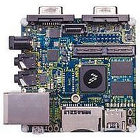
MCIMX53-START
Description
KIT DEVELOPMENT I.MX53
Manufacturer
Freescale Semiconductor
Series
i.MX53r
Type
MCUr
Datasheets
1.MCIMX53-START.pdf
(2 pages)
2.MCIMX53-START.pdf
(180 pages)
3.MCIMX53-START.pdf
(204 pages)
Specifications of MCIMX53-START
Contents
Board
Silicon Manufacturer
Freescale
Core Architecture
ARM
Core Sub-architecture
Cortex - A8
Silicon Core Number
I.MX5
Silicon Family Name
I.MX53
Peak Reflow Compatible (260 C)
Yes
Rohs Compliant
Yes
Leaded Process Compatible
Yes
Lead Free Status / RoHS Status
Lead free / RoHS Compliant
For Use With/related Products
i.MX53
Lead Free Status / Rohs Status
Supplier Unconfirmed
Available stocks
Company
Part Number
Manufacturer
Quantity
Price


Electrical Characteristics
4.7.14
This section describes SATA PHY electrical specifications.
4.7.14.1 Reference Clock Electrical and Jitter Specifications
The refclk signal is differential and supports frequencies of 25 MHz or 50-156.25 MHz (100 MHz and
125 MHz are common frequencies). The frequency is pin-selectable (for more information about the
signal, see “Per-Transceiver Control and Status Signals” in the SATA PHY chapter in the Reference
Manual).
Table 76
124
Differential peak voltage (typically 0.71 V)
Common mode voltage
(refclk_p + refclk_m) / 2
Total phase jitter
Minimum/maximum duty cycle
Frequency range
Parameter
trfs1
ATA
tcvh
tmli
tss
—
—
tli
tli
tli
provides the SATA PHY reference clock specifications.
SATA PHY Parameters
Parameters
Parameter
Figure
Figure
Figure 77
tdzfs_mli
from
i.MX53xA Automotive and Infotainment Applications Processors, Rev. 1
tdzfs
tcvh
trfs
ton
toff
tss
tli1
tli2
tli3
Table 75. UDMA Out Burst Timing Parameters (continued)
75,
76,
trfs = 1.6
tdzfs = time_dzfs
tss = time_ss
tdzfs_mli =max (time_dzfs, time_mli)
tli1 > 0
tli2 > 0
tli3 > 0
tcvh = (time_cvh
ton = time_on
toff = time_off
Table 76. Reference Clock Specifications
×
T + tsui + tco + tbuf + tbuf
×
×
×
T – (tskew1 + tskew2)
T – tskew1
T – tskew1
For information about total
phase jitter, see following
section
×
×
T) – (tskew1 + tskew2)
T – (tskew1)
Test Conditions
Value
—
—
—
—
×
T – (tskew1 + tskew2)
Min
350
175
40
25
—
156.25
Freescale Semiconductor
2,000
Max
850
60
3
Controlling
time_dzfs
time_cvh
Variable
time_ss
—
—
—
—
—
—
mV
mV
ps RMS
% UI
MHz
Unit
Related parts for MCIMX53-START
Image
Part Number
Description
Manufacturer
Datasheet
Request
R

Part Number:
Description:
MCIMX-LVDS1
Manufacturer:
Freescale Semiconductor
Datasheet:

Part Number:
Description:
Manufacturer:
Freescale Semiconductor, Inc
Datasheet:
Part Number:
Description:
Manufacturer:
Freescale Semiconductor, Inc
Datasheet:
Part Number:
Description:
Manufacturer:
Freescale Semiconductor, Inc
Datasheet:
Part Number:
Description:
Manufacturer:
Freescale Semiconductor, Inc
Datasheet:
Part Number:
Description:
Manufacturer:
Freescale Semiconductor, Inc
Datasheet:
Part Number:
Description:
Manufacturer:
Freescale Semiconductor, Inc
Datasheet:
Part Number:
Description:
Manufacturer:
Freescale Semiconductor, Inc
Datasheet:
Part Number:
Description:
Manufacturer:
Freescale Semiconductor, Inc
Datasheet:
Part Number:
Description:
Manufacturer:
Freescale Semiconductor, Inc
Datasheet:
Part Number:
Description:
Manufacturer:
Freescale Semiconductor, Inc
Datasheet:
Part Number:
Description:
Manufacturer:
Freescale Semiconductor, Inc
Datasheet:
Part Number:
Description:
Manufacturer:
Freescale Semiconductor, Inc
Datasheet:
Part Number:
Description:
Manufacturer:
Freescale Semiconductor, Inc
Datasheet:
Part Number:
Description:
Manufacturer:
Freescale Semiconductor, Inc
Datasheet: