MCIMX53-START Freescale Semiconductor, MCIMX53-START Datasheet - Page 19
MCIMX53-START
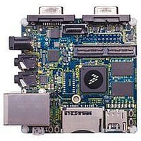
Manufacturer Part Number
MCIMX53-START
Description
KIT DEVELOPMENT I.MX53
Manufacturer
Freescale Semiconductor
Series
i.MX53r
Type
MCUr
Datasheets
1.MCIMX53-START.pdf
(2 pages)
2.MCIMX53-START.pdf
(180 pages)
3.MCIMX53-START.pdf
(204 pages)
Specifications of MCIMX53-START
Contents
Board
Silicon Manufacturer
Freescale
Core Architecture
ARM
Core Sub-architecture
Cortex - A8
Silicon Core Number
I.MX5
Silicon Family Name
I.MX53
Peak Reflow Compatible (260 C)
Yes
Rohs Compliant
Yes
Leaded Process Compatible
Yes
Lead Free Status / RoHS Status
Lead free / RoHS Compliant
For Use With/related Products
i.MX53
Lead Free Status / Rohs Status
Supplier Unconfirmed
Available stocks
Company
Part Number
Manufacturer
Quantity
Price


4.1.2
Table 5
4.1.3
Table 6
Freescale Semiconductor
1
2
3
4
5
6
Junction to Ambient (natural convection)
Junction to Ambient (natural convection)
Junction to Ambient (@200 ft/min)
Junction to Ambient (@200 ft/min)
Junction to Board
Junction to Case
Junction to Package Top (natural convection)
Junction temperature is a function of die size, on-chip power dissipation, package thermal resistance, mounting site (board)
temperature, ambient temperature, air flow, power dissipation of other components on the board, and board thermal
resistance.
Per JEDEC JESD51-2 with the single layer board horizontal. Board meets JESD51-9 specification.
Per JEDEC JESD51-6 with the board horizontal.
Thermal resistance between the die and the printed circuit board per JEDEC JESD51-8. Board temperature is measured on
the top surface of the board near the package.
Thermal resistance between the die and the case top surface as measured by the cold plate method (MIL SPEC-883 Method
1012.1).
Thermal characterization parameter indicating the temperature difference between package top and the junction temperature
per JEDEC JESD51-2.
Symbol
VDDGP
provides the package thermal resistance data.
provides the operating ranges of i.MX53xA processor.
VDDA
VCC
Thermal Resistance
Operating Ranges
3
5
4
i.MX53xA Automotive and Infotainment Applications Processors, Rev. 1
Rating
ARM core supply voltage
f
ARM core supply voltage
Stop mode
Peripheral supply voltage
Peripheral supply voltage—Stop mode
Memory arrays voltage
Memory arrays voltage—Stop mode
ARM
≤
1, 3
1, 3
800 MHz
Table 5. Package Thermal Resistance Data
1, 2
1, 2, 3
Table 6. i.MX53xA Operating Ranges
6
Parameter
Single layer board
Single layer board
Four layer board
Four layer board
Board
(2s2p)
(2s2p)
(1s)
(1s)
—
—
—
Minimum
1.05
1.25
1.25
Symbol
0.8
0.9
0.9
R
R
R
R
R
R
Ψ
θJMA
θJMA
θJC
θJA
θJA
θJB
JT
1
Nominal
0.85
0.95
1.30
0.95
1.1
1.3
Electrical Characteristics
Value
28
16
21
13
2
6
4
4
Maximum
1.15
1.15
1.35
1.35
1.35
1.35
°C/W
°C/W
°C/W
°C/W
°C/W
°C/W
°C/W
1
Unit
Unit
V
V
V
V
V
V
19
Related parts for MCIMX53-START
Image
Part Number
Description
Manufacturer
Datasheet
Request
R

Part Number:
Description:
MCIMX-LVDS1
Manufacturer:
Freescale Semiconductor
Datasheet:

Part Number:
Description:
Manufacturer:
Freescale Semiconductor, Inc
Datasheet:
Part Number:
Description:
Manufacturer:
Freescale Semiconductor, Inc
Datasheet:
Part Number:
Description:
Manufacturer:
Freescale Semiconductor, Inc
Datasheet:
Part Number:
Description:
Manufacturer:
Freescale Semiconductor, Inc
Datasheet:
Part Number:
Description:
Manufacturer:
Freescale Semiconductor, Inc
Datasheet:
Part Number:
Description:
Manufacturer:
Freescale Semiconductor, Inc
Datasheet:
Part Number:
Description:
Manufacturer:
Freescale Semiconductor, Inc
Datasheet:
Part Number:
Description:
Manufacturer:
Freescale Semiconductor, Inc
Datasheet:
Part Number:
Description:
Manufacturer:
Freescale Semiconductor, Inc
Datasheet:
Part Number:
Description:
Manufacturer:
Freescale Semiconductor, Inc
Datasheet:
Part Number:
Description:
Manufacturer:
Freescale Semiconductor, Inc
Datasheet:
Part Number:
Description:
Manufacturer:
Freescale Semiconductor, Inc
Datasheet:
Part Number:
Description:
Manufacturer:
Freescale Semiconductor, Inc
Datasheet:
Part Number:
Description:
Manufacturer:
Freescale Semiconductor, Inc
Datasheet: