MCIMX53-START Freescale Semiconductor, MCIMX53-START Datasheet - Page 114
MCIMX53-START
Manufacturer Part Number
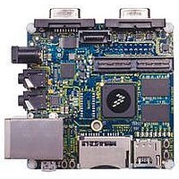
MCIMX53-START
Description
KIT DEVELOPMENT I.MX53
Manufacturer
Freescale Semiconductor
Series
i.MX53r
Type
MCUr
Datasheets
1.MCIMX53-START.pdf
(2 pages)
2.MCIMX53-START.pdf
(180 pages)
3.MCIMX53-START.pdf
(204 pages)
Specifications of MCIMX53-START
Contents
Board
Silicon Manufacturer
Freescale
Core Architecture
ARM
Core Sub-architecture
Cortex - A8
Silicon Core Number
I.MX5
Silicon Family Name
I.MX53
Peak Reflow Compatible (260 C)
Yes
Rohs Compliant
Yes
Leaded Process Compatible
Yes
Lead Free Status / RoHS Status
Lead free / RoHS Compliant
For Use With/related Products
i.MX53
Lead Free Status / Rohs Status
Supplier Unconfirmed
Available stocks
Company
Part Number
Manufacturer
Quantity
Price


Electrical Characteristics
4.7.12
This section describes the electrical information of the PWM. The PWM can be programmed to select one
of three clock signals as its source frequency. The selected clock signal is passed through a prescaler before
being input to the counter. The output is available at the pulse-width modulator output (PWMO) external
pin.
Figure 66
114
OW10
OW11
OW7
OW8
OW9
One-Wire bus
(BATT_LINE)
ID
depicts the timing of the PWM, and
Pulse Width Modulator (PWM) Timing Parameters
Write 1 Low Time
Transmission Time Slot
Read Data Setup
Read Low Time
Read Data Valid
Release Time
System Clock
i.MX53xA Automotive and Infotainment Applications Processors, Rev. 1
PWM Output
Parameter
t
SU
OW9
Figure 65. Read Sequence Timing Diagram
Table 67. WR1 /RD Timing Parameters
OW10
Figure 66. PWM Timing
2a
4a
Table 68
2b
OW8
t
Symbol
RELEASE
t
t
t
OW11
LOWR
LOW1
t
SLOT
t
RDV
SU
lists the PWM timing parameters.
1
3a
Min
60
—
—
1
1
0
Typ
117
15
—
—
5
5
3b
4b
Freescale Semiconductor
Max
120
15
15
45
—
1
Unit
µs
µs
µs
µs
µs
µs
Related parts for MCIMX53-START
Image
Part Number
Description
Manufacturer
Datasheet
Request
R

Part Number:
Description:
MCIMX-LVDS1
Manufacturer:
Freescale Semiconductor
Datasheet:

Part Number:
Description:
Manufacturer:
Freescale Semiconductor, Inc
Datasheet:
Part Number:
Description:
Manufacturer:
Freescale Semiconductor, Inc
Datasheet:
Part Number:
Description:
Manufacturer:
Freescale Semiconductor, Inc
Datasheet:
Part Number:
Description:
Manufacturer:
Freescale Semiconductor, Inc
Datasheet:
Part Number:
Description:
Manufacturer:
Freescale Semiconductor, Inc
Datasheet:
Part Number:
Description:
Manufacturer:
Freescale Semiconductor, Inc
Datasheet:
Part Number:
Description:
Manufacturer:
Freescale Semiconductor, Inc
Datasheet:
Part Number:
Description:
Manufacturer:
Freescale Semiconductor, Inc
Datasheet:
Part Number:
Description:
Manufacturer:
Freescale Semiconductor, Inc
Datasheet:
Part Number:
Description:
Manufacturer:
Freescale Semiconductor, Inc
Datasheet:
Part Number:
Description:
Manufacturer:
Freescale Semiconductor, Inc
Datasheet:
Part Number:
Description:
Manufacturer:
Freescale Semiconductor, Inc
Datasheet:
Part Number:
Description:
Manufacturer:
Freescale Semiconductor, Inc
Datasheet:
Part Number:
Description:
Manufacturer:
Freescale Semiconductor, Inc
Datasheet: