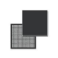
SPEAR300-2 STMicroelectronics, SPEAR300-2 Datasheet - Page 21

SPEAR300-2
Manufacturer Part Number
SPEAR300-2
Description
IC MPU ARM9 289LFBGA
Manufacturer
STMicroelectronics
Series
SPEAr®r
Datasheet
1.SPEAR300-2.pdf
(83 pages)
Specifications of SPEAR300-2
Processor Type
ARM Microprocessor
Speed
333MHz
Voltage
1.14 V ~ 3.6 V
Mounting Type
Surface Mount
Package / Case
289-LFBGA
Processor Series
SPEAr300
Core
ARM926EJ-S
Data Bus Width
16 bit
Maximum Clock Frequency
333 MHz
Operating Supply Voltage
1.2 V
Maximum Operating Temperature
+ 85 C
Mounting Style
SMD/SMT
Data Ram Size
56 KB
Interface Type
I2C, UART, USB, Serial
Number Of Programmable I/os
62
Number Of Timers
6
Program Memory Size
32 KB
Program Memory Type
ROM
Lead Free Status / RoHS Status
Lead free / RoHS Compliant
Features
-
Lead Free Status / Rohs Status
Lead free / RoHS Compliant
Other names
497-10849-5
Available stocks
Company
Part Number
Manufacturer
Quantity
Price
Company:
Part Number:
SPEAR300-2
Manufacturer:
ST
Quantity:
12 005
Part Number:
SPEAR300-2
Manufacturer:
ST
Quantity:
20 000
SPEAr300
2.18
2.19
I
The I
definition. It is composed of 4 signals:
●
●
●
●
The DOUT line can be high impedance when out of samples. Data is always stored in 32 bit
format in the buffer. A shift left operation is possible to left align the data.
Main features:
●
●
●
●
●
●
GPIOs
The General Purpose Input/Outputs (GPIOs) provide programmable inputs or outputs.
Main features:
●
●
●
Up to 62 general purpose I/Os are available in Mode 4 (LEND_IP_ph) (see
●
2
S interface
I2S_LRCK; Left and right channels synchronization (Master/slave)
I2S_CLK: I
I2S_DIN: I
I2S DOUT: I
Can be master or slave for the clock and sync signals
Buffering of up to 1024 samples (512 left and 512 right samples representing 64 ms of
voice). Data is stored always on 32 bits.
Left and right channels are stored in two different buffers.
Two banks are used to exchange data with the processor.
In master mode, LRCK can be adjusted for 8, 16 or 32 bits width.
Data width can be less than LRCK width. Input (received on I2S_DIN) and output
(transmitted on DOUT) can be 8, 16 or 32 bits.
Individually programmable input/output pins implemented in 3 blocks:
–
–
–
–
Programmable interrupt generation capability up to 22 pins.
Base GPIOs and independent GPIOs support bit masking in both read and write
operation through address lines.
In this mode the application can use:
–
–
–
–
–
–
–
2
S interface is very similar to the TDM block, but the frame sync is limited to Philips I
Up to 6 base GPIOs in the basic subsystem (basGPIO)
Up to 18 GPIOs in the RAS subsystem (G10 and G8)
Up to 18 GPIOs in the keyboard controller
Up to 8 GPIOs in the independent GPIO block (GPIO[7:0])
10 GPIOs in G10 block
8 GPIOs in G8 block (0 to 3 in output mode only)
18 GPIO (keyboard controller I/Os in GPIO mode)
6 base GPIOs (basGPIO) (enabled as alternate functions (see
8 IT pins (input only, with interrupt capability)
4 SYNC outputs (SYNC4-7)
8 SPI_I2C outputs
2
2
S clock (Master/slave)
S clock (Master/slave)
2
S output (tri-state)
Doc ID 16324 Rev 2
Architecture overview
Table
Table
11)
10).
21/83
2
S


