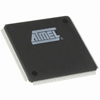
AT91M63200-25AI Atmel, AT91M63200-25AI Datasheet - Page 92

AT91M63200-25AI
Manufacturer Part Number
AT91M63200-25AI
Description
IC ARM7 MCU 176 TQFP
Manufacturer
Atmel
Series
AT91SAMr
Datasheets
1.AT91M43300-25CI.pdf
(21 pages)
2.AT91M43300-25CI.pdf
(5 pages)
3.AT91M63200-25AI.pdf
(12 pages)
4.AT91M63200-25AI.pdf
(153 pages)
Specifications of AT91M63200-25AI
Core Processor
ARM7
Core Size
16/32-Bit
Speed
25MHz
Connectivity
EBI/EMI, SPI, UART/USART
Peripherals
POR, WDT
Number Of I /o
58
Program Memory Type
OTP
Ram Size
2K x 8
Voltage - Supply (vcc/vdd)
1.8 V ~ 3.6 V
Oscillator Type
External
Operating Temperature
-40°C ~ 85°C
Package / Case
176-TQFP, 176-VQFP
Lead Free Status / RoHS Status
Contains lead / RoHS non-compliant
Eeprom Size
-
Program Memory Size
-
Data Converters
-
Available stocks
Company
Part Number
Manufacturer
Quantity
Price
SPI: Serial Peripheral Interface
The AT91M63200 includes an SPI which provides commu-
nication with external devices in master or slave mode.
Pin Description
Seven pins are associated with the SPI interface. When not
needed for the SPI function, each of these pins can be con-
figured as a PIO.
Support for an external master is provided by the PIO Con-
troller multi-driver option. To configure an SPI pin as open-
Figure 46. SPI Block Diagram
Table 12. SPI Pins
Note: After a hardware reset, the SPI clock is disabled by
default (see “PMC: Power Management Controller” on
page 139). The user must configure the Power Manage-
ment Controller before any access to the user interface of
the SPI.
92
Pin Name
Master In Slave Out
Master Out Slave In
Serial Clock
Peripheral Chip Selects
Peripheral Chip Select/
Slave Select
AT91M63200
APB
MCKI
MCKI/32
Mnemonic
NPCS[3:1]
NPCS0/
SPCK
MISO
MOSI
NSS
Serial Peripheral Interface
Interrupt Controller
Advanced
INT
NPCS0/NSS
Master
Master
Master
Master
Master
Master
Mode
Slave
Slave
Slave
Slave
NPCS1
NPCS2
NPCS3
SPCK
MOSI
MISO
drain to support external drivers, set the corresponding bits
in the PIO_MDSR register (see page 70).
An input filter can be enabled on the SPI input pins by set-
ting the corresponding bits in the PIO_IFSR (see page 64).
The NPCS0/NSS pin can function as a peripheral chip
select output or slave select input. Refer to Table 12 for a
description of the SPI pins.
Note: After a hardware reset, the SPI pins are deselected
by default (see “PIO: Parallel I/O Controller” on page 55).
The user must configure the PIO Controller to enable the
corresponding pins for their SPI function. NPCS0/NSS
must be configured as open-drain in the Parallel I/O Con-
troller for multi-master operation.
Function
Serial data input to SPI
Serial data output from SPI
Serial data output from SPI
Serial data input to SPI
Clock output from SPI
Clock input to SPI
Select peripherals
Output: selects peripheral
Input: low causes mode fault
Input: chip select for SPI
Parallel I/O
Controller
NPCS0/NSS
NPCS1
NPCS2
NPCS3
SPCK
MISO
MOSI


