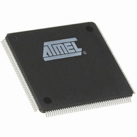
AT91M63200-25AI Atmel, AT91M63200-25AI Datasheet - Page 75

AT91M63200-25AI
Manufacturer Part Number
AT91M63200-25AI
Description
IC ARM7 MCU 176 TQFP
Manufacturer
Atmel
Series
AT91SAMr
Datasheets
1.AT91M43300-25CI.pdf
(21 pages)
2.AT91M43300-25CI.pdf
(5 pages)
3.AT91M63200-25AI.pdf
(12 pages)
4.AT91M63200-25AI.pdf
(153 pages)
Specifications of AT91M63200-25AI
Core Processor
ARM7
Core Size
16/32-Bit
Speed
25MHz
Connectivity
EBI/EMI, SPI, UART/USART
Peripherals
POR, WDT
Number Of I /o
58
Program Memory Type
OTP
Ram Size
2K x 8
Voltage - Supply (vcc/vdd)
1.8 V ~ 3.6 V
Oscillator Type
External
Operating Temperature
-40°C ~ 85°C
Package / Case
176-TQFP, 176-VQFP
Lead Free Status / RoHS Status
Contains lead / RoHS non-compliant
Eeprom Size
-
Program Memory Size
-
Data Converters
-
Available stocks
Company
Part Number
Manufacturer
Quantity
Price
Synchronous Receiver
When configured for synchronous operation (SYNC = 1),
the receiver samples the RXD signal on each rising edge of
the baud rate clock. If a low level is detected, it is consid-
ered as a start. Data bits, parity bit and stop bit are sam-
pled and the receiver waits for the next start bit. See the
example in Figure 43.
Receiver Ready
When a complete character is received, it is transferred to
the US_RHR and the RXRDY status bit in US_CSR is set.
If US_RHR has not been read since the last transfer, the
OVRE status bit in US_CSR is set.
Parity Error
Each time a character is received, the receiver calculates
the parity of the received data bits, in accordance with the
field PAR in US_MR. It then compares the result with the
received parity bit. If different, the parity error bit PARE in
US_CSR is set.
Figure 43. Synchronous Mode: Character Reception
Example: 8-bit, parity enabled 1 stop
Sampling
RXD
SCK
True Start Detection
D0
D1
D2
D3
Framing Error
If a character is received with a stop bit at low level and
with at least one data bit at high level, a framing error is
generated. This sets FRAME in US_CSR.
Time-out
This function allows an idle condition on the RXD line to be
detected. The maximum delay for which the USART should
wait for a new character to arrive while the RXD line is inac-
tive (high level) is programmed in US_RTOR (Receiver
Time-out). When this register is set to 0, no time-out is
detected. Otherwise, the receiver waits for a first character
and then initializes a counter which is decremented at each
bit period and reloaded at each byte reception. When the
counter reaches 0, the TIMEOUT bit in US_CSR is set. The
user can restart the wait for a first character with the
STTTO (Start Time-out) bit in US_CR.
Calculation of time-out duration:
D4
D5
Duration
D6
D7
=
AT91M63200
Value 4
Parity Bit
×
Stop Bit
×
Bit Period
75


