AT91M63200-25AI Atmel, AT91M63200-25AI Datasheet - Page 9
AT91M63200-25AI
Manufacturer Part Number
AT91M63200-25AI
Description
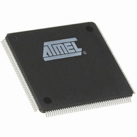
IC ARM7 MCU 176 TQFP
Manufacturer
Atmel
Series
AT91SAMr
Datasheets
1.AT91M43300-25CI.pdf
(21 pages)
2.AT91M43300-25CI.pdf
(5 pages)
3.AT91M63200-25AI.pdf
(12 pages)
4.AT91M63200-25AI.pdf
(153 pages)
Specifications of AT91M63200-25AI
Core Processor
ARM7
Core Size
16/32-Bit
Speed
25MHz
Connectivity
EBI/EMI, SPI, UART/USART
Peripherals
POR, WDT
Number Of I /o
58
Program Memory Type
OTP
Ram Size
2K x 8
Voltage - Supply (vcc/vdd)
1.8 V ~ 3.6 V
Oscillator Type
External
Operating Temperature
-40°C ~ 85°C
Package / Case
176-TQFP, 176-VQFP
Lead Free Status / RoHS Status
Contains lead / RoHS non-compliant
Eeprom Size
-
Program Memory Size
-
Data Converters
-
Available stocks
Company
Part Number
Manufacturer
Quantity
Price


Initialization
Reset
Reset initializes the user interface registers to their default
states as defined in the peripheral sections of this
datasheet and forces the ARM7TDMI to perform the next
instruction fetch from address zero. Except for the program
counter, the ARM core registers do not have defined reset
states. When reset is active, the inputs of the AT91M63200
must be held at valid logic levels. The EBI address lines
drive low during reset. All the peripheral clocks are disabled
during reset to save power (see "PMC: Power Manage-
ment Controller" on page 139).
NRST Pin
NRST is the active low reset input. It is asserted asynchro-
nously, but exit from reset is synchronized internally to
MCKI. MCKI must be active within specification for a mini-
mum of 10 clock cycles up to the rising edge of NRST to
ensure correct operation.
The pins BMS and NTRI are sampled during the 10 clock
cycles just prior to the rising edge of NRST.
The NRST pin has no effect on the on-chip embedded ICE
logic.
Watchdog Reset
The internally-generated watchdog reset has the same
effect as the NRST pin, except that the pins BMS and TRI
are not sampled. Boot mode and tristate mode are not
updated. The NRST pin has priority if both types of reset
coincide.
Boot Mode Select
The input level on the BMS pin during the last 10 clock
cycles before the rising edge of NRST selects the type of
boot memory. Boot operation is described on page 14.
BMS must be driven to a valid logic value during reset.
The boot mode depends on BMS and whether the device
has on-chip nonvolatile memory (NVM). See Table 3
below.
The correct logic level on BMS can be ensured with a resis-
tor (pull-up or pull-down). See “AT91M63200 Electrical and
Mechanical Characteristics” for the resistor value specifica-
tion.
The BMS pin is multiplexed with parallel I/O PB18, which
can be programmed after reset like any standard PIO.
Table 3. Boot Mode Select
BMS
1
0
Architecture
No NVM
NVM on-chip
All
Boot Mode
External 8-bit memory on NCS0
Internal 32-bit NVM
External 16-bit memory on NCS0
Emulation Functions
Tristate Mode
The AT91M63200 provides a tristate mode, which is used
for debug purposes in order to connect an emulator probe
to an application board. In tristate mode the AT91M63200
continues to function, but all the output pin drivers are
tristated.
To enter tristate mode, the pin NTRI must be held low dur-
ing the last 10 clock cycles before the rising edge of NRST.
For normal operation, the pin NTRI must be held high dur-
ing reset by a resistor of up to 400K Ω . NTRI must be driven
to a valid logic value during reset.
NTRI is multiplexed with parallel I/O P21 and USART 1
serial data transmit line TXD1.
Standard RS232 drivers generally contain internal 400K Ω
pull-up resistors. If TXD1 is connected to one of these driv-
ers, this pull-up will ensure normal operation without the
need for an additional external resistor.
Embedded ICE
ARM standard embedded In-Circuit Emulation is supported
via the JTAG/ICE port. It is connected to a host computer
via an embedded ICE interface.
Embedded ICE mode is selected when JTAGSEL is low.
It is not possible to switch directly between ICE and JTAG
operations. A chip reset must be performed (NRST and
NTRST) after JTAGSEL is changed. The reset input to the
embedded ICE (NTRST) is provided separately to facilitate
debug of boot programs.
IEEE 1149.1 JTAG Boundary Scan
IEEE 1149.1 JTAG Boundary Scan is enabled when JTAG-
SEL is high. The functions SAMPLE, EXTEST and
BYPASS are implemented.
In ICE Debug mode, the ARM core responds with a non-
JTAG chip ID, which identifies the core to the ICE system.
This is not IEEE 1149.1 JTAG compliant. See "SF: Special
Function Registers" on page 145 for details on chip ID.
It is not possible to switch directly between JTAG and ICE
operations. A chip reset must be performed (NRST and
NTRST) after JTAGSEL is changed.
AT91M63200
9
Related parts for AT91M63200-25AI
Image
Part Number
Description
Manufacturer
Datasheet
Request
R

Part Number:
Description:
DEV KIT FOR AVR/AVR32
Manufacturer:
Atmel
Datasheet:

Part Number:
Description:
INTERVAL AND WIPE/WASH WIPER CONTROL IC WITH DELAY
Manufacturer:
ATMEL Corporation
Datasheet:
Part Number:
Description:
Low-Voltage Voice-Switched IC for Hands-Free Operation
Manufacturer:
ATMEL Corporation
Datasheet:
Part Number:
Description:
MONOLITHIC INTEGRATED FEATUREPHONE CIRCUIT
Manufacturer:
ATMEL Corporation
Datasheet:
Part Number:
Description:
AM-FM Receiver IC U4255BM-M
Manufacturer:
ATMEL Corporation
Datasheet:
Part Number:
Description:
Monolithic Integrated Feature Phone Circuit
Manufacturer:
ATMEL Corporation
Datasheet:
Part Number:
Description:
Multistandard Video-IF and Quasi Parallel Sound Processing
Manufacturer:
ATMEL Corporation
Datasheet:
Part Number:
Description:
High-performance EE PLD
Manufacturer:
ATMEL Corporation
Datasheet:
Part Number:
Description:
8-bit Flash Microcontroller
Manufacturer:
ATMEL Corporation
Datasheet:
Part Number:
Description:
2-Wire Serial EEPROM
Manufacturer:
ATMEL Corporation
Datasheet: