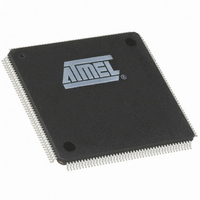
AT91M63200-25AI Atmel, AT91M63200-25AI Datasheet - Page 72

AT91M63200-25AI
Manufacturer Part Number
AT91M63200-25AI
Description
IC ARM7 MCU 176 TQFP
Manufacturer
Atmel
Series
AT91SAMr
Datasheets
1.AT91M43300-25CI.pdf
(21 pages)
2.AT91M43300-25CI.pdf
(5 pages)
3.AT91M63200-25AI.pdf
(12 pages)
4.AT91M63200-25AI.pdf
(153 pages)
Specifications of AT91M63200-25AI
Core Processor
ARM7
Core Size
16/32-Bit
Speed
25MHz
Connectivity
EBI/EMI, SPI, UART/USART
Peripherals
POR, WDT
Number Of I /o
58
Program Memory Type
OTP
Ram Size
2K x 8
Voltage - Supply (vcc/vdd)
1.8 V ~ 3.6 V
Oscillator Type
External
Operating Temperature
-40°C ~ 85°C
Package / Case
176-TQFP, 176-VQFP
Lead Free Status / RoHS Status
Contains lead / RoHS non-compliant
Eeprom Size
-
Program Memory Size
-
Data Converters
-
Available stocks
Company
Part Number
Manufacturer
Quantity
Price
USART: Universal Synchronous/Asynchronous Receiver/Transmitter
The AT91M63200 provides three identical, full-duplex, uni-
versal synchronous/asynchronous receiver/transmitters
that interface to the APB and are connected to the Periph-
eral Data Controller.
The main features are:
•
•
Figure 39. USART Block Diagram
Pin Description
Each USART channel has the following external signals:
Note: After a hardware reset, the USART clock is disabled
by default (see “PMC: Power Management Controller” on
page 139). The user must configure the Power Manage-
ment Controller before any access to the user interface of
the USART.
72
Programmable baud rate generator
Parity, framing and overrun error detection
Name
SCK
RXD
TXD
USxIRQ
MCKI/8
MCKI
Description
USART serial clock can be configured as input or output:
SCK is configured as input if an external clock is selected (USCLKS[1] = 1)
SCK is driven as output if the external clock is disabled (USCLKS[1] = 0) and clock output is enabled (CLKO = 1)
Transmit Serial Data is an output
Receive Serial Data is an input
ASB
APB
AMBA
AT91M63200
Peripheral Data Controller
Baud Rate Generator
Receiver
Channel
Interrupt Control
Control Logic
Transmitter
Channel
Baud Rate Clock
•
•
•
•
•
•
Note: After a hardware reset, the USART pins are dese-
lected by default (see “PIO: Parallel I/O Controller” on
page 55). The user must configure the PIO Controller
before enabling the transmitter or receiver.
If the user selects one of the internal clocks, SCK can be
configured as a PIO.
USART Channel
Line break generation and detection
Automatic echo, local loopback and remote loopback
channel modes
Multi-drop mode: address detection and generation
Interrupt generation
Two dedicated peripheral data controller channels
5-, 6-, 7-, 8- and 9-bit character length
Transmitter
Receiver
Controller
Parallel
PIO:
I/O
RXD
TXD
SCK


