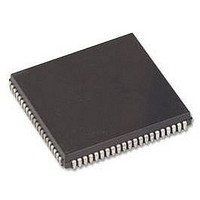
HD64F3337YCP16V Renesas Electronics America, HD64F3337YCP16V Datasheet - Page 106

HD64F3337YCP16V
Manufacturer Part Number
HD64F3337YCP16V
Description
MCU 3/5V 60K PB-FREE 84-PLCC
Manufacturer
Renesas Electronics America
Series
H8® H8/300r
Specifications of HD64F3337YCP16V
Core Size
8-Bit
Program Memory Size
60KB (60K x 8)
Oscillator Type
Internal
Core Processor
H8/300
Speed
16MHz
Connectivity
Host Interface, I²C, SCI
Peripherals
POR, PWM, WDT
Number Of I /o
74
Program Memory Type
FLASH
Ram Size
2K x 8
Voltage - Supply (vcc/vdd)
4.5 V ~ 5.5 V
Data Converters
A/D 8x10b; D/A 2x8b
Operating Temperature
-20°C ~ 75°C
Package / Case
84-PLCC
No. Of I/o's
74
Ram Memory Size
1KB
Cpu Speed
16MHz
No. Of Timers
6
No. Of Pwm Channels
2
Digital Ic Case Style
PLCC
Controller Family/series
H8/300
Rohs Compliant
Yes
Lead Free Status / RoHS Status
Lead free / RoHS Compliant
Eeprom Size
-
Lead Free Status / RoHS Status
Lead free / RoHS Compliant, Lead free / RoHS Compliant
Available stocks
Company
Part Number
Manufacturer
Quantity
Price
Company:
Part Number:
HD64F3337YCP16V
Manufacturer:
COILMASTER
Quantity:
30 000
Company:
Part Number:
HD64F3337YCP16V
Manufacturer:
Renesas Electronics America
Quantity:
10 000
- Current page: 106 of 749
- Download datasheet (4Mb)
4.2.3
After a reset, if an interrupt were to be accepted before initialization of the stack pointer (SP: R7),
the program counter and condition code register might not be saved correctly, leading to a
program crash. To prevent this, all interrupts, including NMI, are disabled immediately after a
reset. The first program instruction is therefore always executed. This instruction should initialize
the stack pointer (example: MOV.W #xx:16, SP).
After reset exception handling, in order to initialize the contents of CCR, a CCR manipulation
instruction can be executed before an instruction to initialize the stack pointer. Immediately after
execution of a CCR manipulation instruction, all interrupts including NMI are disabled. Use the
next instruction to initialize the stack pointer.
4.3
4.3.1
The interrupt sources include nine external sources from 23 input pins (NMI, IRQ
KEYIN
chip supporting modules. Table 4.2 lists the interrupt sources in priority order and gives their
vector addresses. When two or more interrupts are requested, the interrupt with highest priority is
served first.
The features of these interrupts are:
74
NMI has the highest priority and is always accepted. All internal and external interrupts except
NMI can be masked by the I bit in the CCR. When the I bit is set to 1, interrupts other than
NMI are not accepted.
IRQ
sensing can be selected for each interrupt individually. NMI is edge-sensed, and either the
rising or falling edge can be selected.
All interrupts are individually vectored. The software interrupt-handling routine does not have
to determine what type of interrupt has occurred.
IRQ
masked individually by user software.
The watchdog timer can generate either an NMI or overflow interrupt, depending on the needs
of the application. For details, see section 11, Watchdog Timer.
0
0
6
to KEYIN
to IRQ
is multiplexed with 8 external sources (KEYIN
Disabling of Interrupts after Reset
Interrupts
Overview
7
can be sensed on the falling edge of the input signal, or level-sensed. The type of
7
), and 26 (H8/3337 Series) or 23 (H8/3397 Series) internal sources in the on-
0
to KEYIN
7
). KEYIN
0
to KEYIN
0
to IRQ
7
7
, and
can be
Related parts for HD64F3337YCP16V
Image
Part Number
Description
Manufacturer
Datasheet
Request
R

Part Number:
Description:
KIT STARTER FOR M16C/29
Manufacturer:
Renesas Electronics America
Datasheet:

Part Number:
Description:
KIT STARTER FOR R8C/2D
Manufacturer:
Renesas Electronics America
Datasheet:

Part Number:
Description:
R0K33062P STARTER KIT
Manufacturer:
Renesas Electronics America
Datasheet:

Part Number:
Description:
KIT STARTER FOR R8C/23 E8A
Manufacturer:
Renesas Electronics America
Datasheet:

Part Number:
Description:
KIT STARTER FOR R8C/25
Manufacturer:
Renesas Electronics America
Datasheet:

Part Number:
Description:
KIT STARTER H8S2456 SHARPE DSPLY
Manufacturer:
Renesas Electronics America
Datasheet:

Part Number:
Description:
KIT STARTER FOR R8C38C
Manufacturer:
Renesas Electronics America
Datasheet:

Part Number:
Description:
KIT STARTER FOR R8C35C
Manufacturer:
Renesas Electronics America
Datasheet:

Part Number:
Description:
KIT STARTER FOR R8CL3AC+LCD APPS
Manufacturer:
Renesas Electronics America
Datasheet:

Part Number:
Description:
KIT STARTER FOR RX610
Manufacturer:
Renesas Electronics America
Datasheet:

Part Number:
Description:
KIT STARTER FOR R32C/118
Manufacturer:
Renesas Electronics America
Datasheet:

Part Number:
Description:
KIT DEV RSK-R8C/26-29
Manufacturer:
Renesas Electronics America
Datasheet:

Part Number:
Description:
KIT STARTER FOR SH7124
Manufacturer:
Renesas Electronics America
Datasheet:

Part Number:
Description:
KIT STARTER FOR H8SX/1622
Manufacturer:
Renesas Electronics America
Datasheet:

Part Number:
Description:
KIT DEV FOR SH7203
Manufacturer:
Renesas Electronics America
Datasheet:


