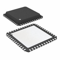
ATA6603P-PLQW Atmel, ATA6603P-PLQW Datasheet - Page 317

ATA6603P-PLQW
Manufacturer Part Number
ATA6603P-PLQW
Description
MCU W/LIN TXRX REG WTCHDG 48-QFN
Manufacturer
Atmel
Series
AVR® ATA66 LIN-SBCr
Datasheet
1.ATA6603P-PLQW.pdf
(360 pages)
Specifications of ATA6603P-PLQW
Core Processor
AVR
Core Size
8-Bit
Speed
16MHz
Connectivity
I²C, LIN, SPI, UART/USART
Peripherals
Brown-out Detect/Reset, POR, PWM, WDT
Number Of I /o
23
Program Memory Size
16KB (16K x 8)
Program Memory Type
FLASH
Eeprom Size
512 x 8
Ram Size
1K x 8
Voltage - Supply (vcc/vdd)
2.7 V ~ 5.5 V
Data Converters
A/D 8x10b
Oscillator Type
Internal
Operating Temperature
-40°C ~ 125°C
Package / Case
48-QFN Exposed Pad
Lead Free Status / RoHS Status
Lead free / RoHS Compliant
Available stocks
Company
Part Number
Manufacturer
Quantity
Price
Company:
Part Number:
ATA6603P-PLQW
Manufacturer:
ATMEL
Quantity:
2 000
Part Number:
ATA6603P-PLQW
Manufacturer:
ATMEL/爱特梅尔
Quantity:
20 000
- Current page: 317 of 360
- Download datasheet (6Mb)
Table 4-128. Serial Programming Instruction Set (Continued)
Note:
4.24.8.4
4921E–AUTO–09/09
Instruction
Write Lock bits
Read Signature Byte
Write Fuse bits
Write Fuse High bits
Write Extended Fuse Bits
Read Fuse bits
Read Fuse High bits
Read Extended Fuse Bits
Read Calibration Byte
Poll RDY/BSY
a = address high bits, b = address low bits, H = 0 - Low byte, 1 - High Byte, o = data out, i = data in, x = do not care
SPI Serial Programming Characteristics
For characteristics of the SPI module see
1010 1100
0011 0000
1010 1100
1010 1100
1010 1100
0101 0000
0101 1000
0101 0000
0011 1000
1111 0000
Byte 1
111x xxxx
000x xxxx
1010 0000
1010 1000
1010 0100
0000 0000
0000 1000
0000 1000
000x xxxx
0000 0000
Byte 2
Instruction Format
xxxx xxxx
xxxx xxbb
xxxx xxxx
xxxx xxxx
xxxx xxxx
xxxx xxxx
xxxx xxxx
xxxx xxxx
0000 0000
xxxx xxxx
Byte 3
“SPI Timing Characteristics” on page
11ii iiii Write Lock bits. Set bits = “0” to program
oooo oooo Read Signature Byte o at address b.
iiii iiii Set bits = “0” to program, “1” to
iiii iiii Set bits = “0” to program, “1” to
xxxx xxii Set bits = “0” to program, “1” to
oooo oooo Read Fuse bits. “0” = programmed, “1” =
oooo oooo Read Fuse High bits. “0” = programmed,
oooo oooo Read Extended Fuse bits. “0” =
oooo oooo Read Calibration Byte
xxxx xxxo If o = “1”, a programming operation is still
Byte4
Operation
Lock bits. See
for details.
unprogram. See Table XXX on page
XXX for details.
unprogram. See
for details.
unprogram. See
300
unprogrammed. See Table XXX on
page XXX for details.
“1” = unprogrammed. See
page 268
programmed, “1” = unprogrammed. See
Table 4-116 on page 300
busy. Wait until this bit returns to “0”
before applying another command.
ATA6602/ATA6603
for details.
for details.
Table 4-113 on page 298
Table 4-97 on page 268
Table 4-116 on page
324.
for details.
Table 4-97 on
317
Related parts for ATA6603P-PLQW
Image
Part Number
Description
Manufacturer
Datasheet
Request
R

Part Number:
Description:
MCU, MPU & DSP Development Tools Demoboard LIN-MCM
Manufacturer:
Atmel
Datasheet:

Part Number:
Description:
Microcontroller With Lin Transceiver, 5v Regulator And Watchdog
Manufacturer:
ATMEL Corporation
Datasheet:

Part Number:
Description:
DEV KIT FOR AVR/AVR32
Manufacturer:
Atmel
Datasheet:

Part Number:
Description:
INTERVAL AND WIPE/WASH WIPER CONTROL IC WITH DELAY
Manufacturer:
ATMEL Corporation
Datasheet:

Part Number:
Description:
Low-Voltage Voice-Switched IC for Hands-Free Operation
Manufacturer:
ATMEL Corporation
Datasheet:

Part Number:
Description:
MONOLITHIC INTEGRATED FEATUREPHONE CIRCUIT
Manufacturer:
ATMEL Corporation
Datasheet:

Part Number:
Description:
AM-FM Receiver IC U4255BM-M
Manufacturer:
ATMEL Corporation
Datasheet:

Part Number:
Description:
Monolithic Integrated Feature Phone Circuit
Manufacturer:
ATMEL Corporation
Datasheet:

Part Number:
Description:
Multistandard Video-IF and Quasi Parallel Sound Processing
Manufacturer:
ATMEL Corporation
Datasheet:

Part Number:
Description:
High-performance EE PLD
Manufacturer:
ATMEL Corporation
Datasheet:

Part Number:
Description:
8-bit Flash Microcontroller
Manufacturer:
ATMEL Corporation
Datasheet:

Part Number:
Description:
2-Wire Serial EEPROM
Manufacturer:
ATMEL Corporation
Datasheet:


