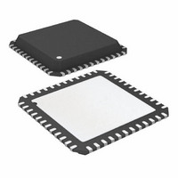
ATA6603P-PLQW Atmel, ATA6603P-PLQW Datasheet - Page 16

ATA6603P-PLQW
Manufacturer Part Number
ATA6603P-PLQW
Description
MCU W/LIN TXRX REG WTCHDG 48-QFN
Manufacturer
Atmel
Series
AVR® ATA66 LIN-SBCr
Datasheet
1.ATA6603P-PLQW.pdf
(360 pages)
Specifications of ATA6603P-PLQW
Core Processor
AVR
Core Size
8-Bit
Speed
16MHz
Connectivity
I²C, LIN, SPI, UART/USART
Peripherals
Brown-out Detect/Reset, POR, PWM, WDT
Number Of I /o
23
Program Memory Size
16KB (16K x 8)
Program Memory Type
FLASH
Eeprom Size
512 x 8
Ram Size
1K x 8
Voltage - Supply (vcc/vdd)
2.7 V ~ 5.5 V
Data Converters
A/D 8x10b
Oscillator Type
Internal
Operating Temperature
-40°C ~ 125°C
Package / Case
48-QFN Exposed Pad
Lead Free Status / RoHS Status
Lead free / RoHS Compliant
Available stocks
Company
Part Number
Manufacturer
Quantity
Price
Company:
Part Number:
ATA6603P-PLQW
Manufacturer:
ATMEL
Quantity:
2 000
Part Number:
ATA6603P-PLQW
Manufacturer:
ATMEL/爱特梅尔
Quantity:
20 000
- Current page: 16 of 360
- Download datasheet (6Mb)
3.3.18
3.3.18.1
16
ATA6602/ATA6603
Watchdog
Typical Timing Sequence with R
Figure 3-9.
For programming purposes at the microcontroller it is potentially necessary to supply the VCC
output via an external supply while the VS pin of the system basis chip is disconnected. This
behavior is no problem for the system basis chip.
The watchdog anticipates a trigger signal from the microcontroller at the NTRIG (negative edge)
or the PTRIG (positive edge) input within a period time window of T
exceed a minimum time t
generated at output NRES. The timing basis of the watchdog is provided by the internal oscilla-
tor, of which the time period t
In Silent or Sleep mode, the watchdog is switched off to reduce current consumption.
Minimum time for first watchdog pulse is required after the undervoltage reset at NRES disap-
pears and is defined as lead time t
The trigger signal T
For example, with an external resistor of R
watchdog come out as follows:
t
t
t
t
t
After every reset the watchdog always starts with the lead time.
OSC
d
1
2
nres
= 3922
= 800
= 840
= 157
= 12.5 µs due to 51 k
12.5 µs = 10 ms
12.5 µs = 10.5 ms
12.5 µs = 49 ms
12.5 µs = 1.96 ms
Power Dissipation: Safe Operating Area versus V
Voltage V
wd_osc
wd
is adjustable between 2.9 ms and 33 ms via the external resistor R
40
30
20
50
45
35
25
55
10
15
0
S
5
= 51 k
trigmin
5
at Different Ambient Temperatures T
osc
6
> 3 µs. If a triggering signal is not received, a reset signal will be
is adjustable via the external resistor R
7
d
.
8
9
10
wd_oscSC
11
V
S
12
(V)
= 51 k ±1%, the typical parameters of the
13
14
15
case
DD
16
125˚C
105˚C
with R
Output Current and Supply
17
wd
. The trigger signal must
wd_osc
18
thJA
19
= 35 K/W
(10 k to 120 k ).
4921E–AUTO–09/09
wd_osc
.
Related parts for ATA6603P-PLQW
Image
Part Number
Description
Manufacturer
Datasheet
Request
R

Part Number:
Description:
MCU, MPU & DSP Development Tools Demoboard LIN-MCM
Manufacturer:
Atmel
Datasheet:

Part Number:
Description:
Microcontroller With Lin Transceiver, 5v Regulator And Watchdog
Manufacturer:
ATMEL Corporation
Datasheet:

Part Number:
Description:
DEV KIT FOR AVR/AVR32
Manufacturer:
Atmel
Datasheet:

Part Number:
Description:
INTERVAL AND WIPE/WASH WIPER CONTROL IC WITH DELAY
Manufacturer:
ATMEL Corporation
Datasheet:

Part Number:
Description:
Low-Voltage Voice-Switched IC for Hands-Free Operation
Manufacturer:
ATMEL Corporation
Datasheet:

Part Number:
Description:
MONOLITHIC INTEGRATED FEATUREPHONE CIRCUIT
Manufacturer:
ATMEL Corporation
Datasheet:

Part Number:
Description:
AM-FM Receiver IC U4255BM-M
Manufacturer:
ATMEL Corporation
Datasheet:

Part Number:
Description:
Monolithic Integrated Feature Phone Circuit
Manufacturer:
ATMEL Corporation
Datasheet:

Part Number:
Description:
Multistandard Video-IF and Quasi Parallel Sound Processing
Manufacturer:
ATMEL Corporation
Datasheet:

Part Number:
Description:
High-performance EE PLD
Manufacturer:
ATMEL Corporation
Datasheet:

Part Number:
Description:
8-bit Flash Microcontroller
Manufacturer:
ATMEL Corporation
Datasheet:

Part Number:
Description:
2-Wire Serial EEPROM
Manufacturer:
ATMEL Corporation
Datasheet:


