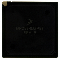
MPC564MZP56 Freescale Semiconductor, MPC564MZP56 Datasheet - Page 941

MPC564MZP56
Manufacturer Part Number
MPC564MZP56
Description
IC MCU 512K FLASH 56MHZ 388-BGA
Manufacturer
Freescale Semiconductor
Series
MPC5xxr
Specifications of MPC564MZP56
Core Processor
PowerPC
Core Size
32-Bit
Speed
56MHz
Connectivity
CAN, EBI/EMI, SCI, SPI, UART/USART
Peripherals
POR, PWM, WDT
Number Of I /o
56
Program Memory Size
512KB (512K x 8)
Program Memory Type
FLASH
Ram Size
32K x 8
Voltage - Supply (vcc/vdd)
2.5 V ~ 2.7 V
Data Converters
A/D 32x10b
Oscillator Type
External
Operating Temperature
-40°C ~ 125°C
Package / Case
388-BGA
Core
PowerPC
Processor Series
MPC5xx
Data Bus Width
32 bit
Maximum Clock Frequency
56 MHz
Data Ram Size
32 KB
On-chip Adc
Yes
Number Of Programmable I/os
56
Number Of Timers
2
Operating Supply Voltage
0 V to 5 V
Mounting Style
SMD/SMT
A/d Bit Size
10 bit
A/d Channels Available
32
Height
1.95 mm
Interface Type
CAN, JTAG, QSPI, SCI, SPI, UART
Length
27 mm
Maximum Operating Temperature
+ 125 C
Minimum Operating Temperature
- 40 C
Supply Voltage (max)
2.7 V, 5.25 V
Supply Voltage (min)
2.5 V, 4.75 V
Width
27 mm
For Use With
MPC564EVB - KIT EVAL FOR MPC561/562/563/564
Lead Free Status / RoHS Status
Contains lead / RoHS non-compliant
Eeprom Size
-
Lead Free Status / Rohs Status
No RoHS Version Available
Available stocks
Company
Part Number
Manufacturer
Quantity
Price
Company:
Part Number:
MPC564MZP56
Manufacturer:
FREESCAL
Quantity:
364
Company:
Part Number:
MPC564MZP56
Manufacturer:
Freescale Semiconductor
Quantity:
10 000
Part Number:
MPC564MZP56
Manufacturer:
FREESCALE
Quantity:
20 000
Company:
Part Number:
MPC564MZP56R2
Manufacturer:
Freescale Semiconductor
Quantity:
10 000
- Current page: 941 of 1420
- Download datasheet (11Mb)
0, debug mode is enabled and the check stop enable bit in the debug enable register (DER) is set, the CPU
enters debug mode rather then the check stop state.
The different actions taken by the CPU when a machine check interrupt is detected are shown in the
following table.
23.3.1.4
If entering debug mode was as a result of any load/store type exception, and therefore the DAR (data
address register) and DSISR (data storage interrupt status register) have some significant value, these two
registers must be saved before any other operation is performed. Failing to save these registers may result
in loss of their value in case of another load/store type exception inside the development software.
Since exceptions are treated differently when in debug mode (refer to
Mode”), there is no need to save machine status save/restore zero register (SRR0) and machine status
save/restore one register (SRR1).
23.3.1.5
When running in debug mode all fetch cycles access the development port regardless of the actual address
of the cycle. All load/store cycles access the real memory system according to the cycle’s address. The data
register of the development port is mapped as a special control register therefore it is accessed using mtspr
and mfspr instructions via special load/store cycles (refer to
Register
Exceptions are treated differently when running in debug mode. When already in debug mode, upon
recognition of an exception, the exception cause register (ECR) is updated according to the event that
caused the exception, a special error indication (ecr_or) is asserted for one clock cycle to report to the
development port that an exception occurred and execution continues in debug mode without any change
in SRR0 and SRR1. ECR_OR is asserted before the next fetch occurs to allow the development system to
detect the excepting instruction.
Freescale Semiconductor
1
2
MSR[ME]
Check stop enable bit in the debug enable register (DER)
Machine check interrupt enable bit in the debug enable register (DER)
(DPDR)”).
0
1
0
0
1
1
Saving Machine State upon Entering Debug Mode
Running in Debug Mode
Enable
Debug
Mode
0
0
1
1
1
1
CHSTPE
Table 23-9. Check Stop State and Debug Mode
X
X
X
X
0
1
MPC561/MPC563 Reference Manual, Rev. 1.2
1
MCIE
X
X
X
X
0
1
2
Detecting a Machine Check Interrupt
Enter the check stop state
Branch to the machine check interrupt
Enter the check stop state
Enter Debug Mode
Branch to the machine check interrupt
Enter Debug Mode
Action Performed by the CPU when
Section 23.6.13, “Development Port Data
Section 23.3.1.5, “Running in Debug
Exception Cause
Register (ECR)
0x2000_0000
0x2000_0000
0x1000_0000
0x2000_0000
0x1000_0000
0x1000_0000
Development Support
Value
23-27
Related parts for MPC564MZP56
Image
Part Number
Description
Manufacturer
Datasheet
Request
R

Part Number:
Description:
MPC5 1K0 5%
Manufacturer:
TE Connectivity
Datasheet:

Part Number:
Description:
MPC5 500R 5%
Manufacturer:
TE Connectivity
Datasheet:

Part Number:
Description:
MPC5 5K0 5%
Manufacturer:
Tyco Electronics
Datasheet:

Part Number:
Description:
MPC5 5R0 5%
Manufacturer:
Tyco Electronics
Datasheet:

Part Number:
Description:
MPC5 50K 5%
Manufacturer:
Tyco Electronics
Datasheet:

Part Number:
Description:
MPC5 1R0 5%
Manufacturer:
Tyco Electronics
Datasheet:
Part Number:
Description:
Manufacturer:
Freescale Semiconductor, Inc
Datasheet:
Part Number:
Description:
Manufacturer:
Freescale Semiconductor, Inc
Datasheet:
Part Number:
Description:
Manufacturer:
Freescale Semiconductor, Inc
Datasheet:
Part Number:
Description:
Manufacturer:
Freescale Semiconductor, Inc
Datasheet:
Part Number:
Description:
Manufacturer:
Freescale Semiconductor, Inc
Datasheet:


