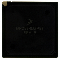
MPC564MZP56 Freescale Semiconductor, MPC564MZP56 Datasheet - Page 495

MPC564MZP56
Manufacturer Part Number
MPC564MZP56
Description
IC MCU 512K FLASH 56MHZ 388-BGA
Manufacturer
Freescale Semiconductor
Series
MPC5xxr
Specifications of MPC564MZP56
Core Processor
PowerPC
Core Size
32-Bit
Speed
56MHz
Connectivity
CAN, EBI/EMI, SCI, SPI, UART/USART
Peripherals
POR, PWM, WDT
Number Of I /o
56
Program Memory Size
512KB (512K x 8)
Program Memory Type
FLASH
Ram Size
32K x 8
Voltage - Supply (vcc/vdd)
2.5 V ~ 2.7 V
Data Converters
A/D 32x10b
Oscillator Type
External
Operating Temperature
-40°C ~ 125°C
Package / Case
388-BGA
Core
PowerPC
Processor Series
MPC5xx
Data Bus Width
32 bit
Maximum Clock Frequency
56 MHz
Data Ram Size
32 KB
On-chip Adc
Yes
Number Of Programmable I/os
56
Number Of Timers
2
Operating Supply Voltage
0 V to 5 V
Mounting Style
SMD/SMT
A/d Bit Size
10 bit
A/d Channels Available
32
Height
1.95 mm
Interface Type
CAN, JTAG, QSPI, SCI, SPI, UART
Length
27 mm
Maximum Operating Temperature
+ 125 C
Minimum Operating Temperature
- 40 C
Supply Voltage (max)
2.7 V, 5.25 V
Supply Voltage (min)
2.5 V, 4.75 V
Width
27 mm
For Use With
MPC564EVB - KIT EVAL FOR MPC561/562/563/564
Lead Free Status / RoHS Status
Contains lead / RoHS non-compliant
Eeprom Size
-
Lead Free Status / Rohs Status
No RoHS Version Available
Available stocks
Company
Part Number
Manufacturer
Quantity
Price
Company:
Part Number:
MPC564MZP56
Manufacturer:
FREESCAL
Quantity:
364
Company:
Part Number:
MPC564MZP56
Manufacturer:
Freescale Semiconductor
Quantity:
10 000
Part Number:
MPC564MZP56
Manufacturer:
FREESCALE
Quantity:
20 000
Company:
Part Number:
MPC564MZP56R2
Manufacturer:
Freescale Semiconductor
Quantity:
10 000
- Current page: 495 of 1420
- Download datasheet (11Mb)
Freescale Semiconductor
10:15
Bits
8:9
Port Signal
Port Signal
Name
Name
PQB0
PQB1
PQB2
PQB3
PQB4
PQB5
PQB6
PQB7
PQA0
PQA1
PQA2
PQA3
PQA4
PQA5
—
—
CHAN
Name
Table 13-19. Non-Multiplexed Channel Assignments and Signal Designations
IST
Analog Signal
Analog Signal
Non-multiplexed Input Signals
Input sample time. The IST field specifies the length of the sample window. Longer sample times
permit more accurate A/D conversions of signals with higher source impedances, especially if
BYP = 1.
00 QCKL period x 2
01 QCKL period x 4
10 QCKL period x 8
11 QCKL period x 16
Channel number. The CHAN field selects the input channel number corresponding to the analog
input signal to be sampled and converted. The analog input signal channel number assignments
and the signal definitions vary depending on whether the QADC64E is operating in multiplexed
or non-multiplexed mode. The queue scan mechanism sees no distinction between an internally
or externally multiplexed analog input.
If CHAN specifies a reserved channel number (channels 32 to 47) or an invalid channel number
(channels 4 to 31 in non-multiplexed mode), the low reference level (VRL) is converted.
Programming the channel field to channel 63 indicates the end of the queue. Channels 60 to 62
are special internal channels. When one of these channels is selected, the sample amplifier is
not used. The value of VRL, VRH, or (V
Programming the input sample time to any value other than two for one of the internal channels
has no benefit except to lengthen the overall conversion time.
Table 13-19
shows the channel number assignments for multiplexed mode.
Name
Name
AN48
AN49
AN50
AN51
AN52
AN53
AN54
AN55
AN56
AN57
AN0
AN1
AN2
AN3
—
—
Table 13-18. CCW Bit Descriptions (continued)
shows the channel number assignments for non-multiplexed mode.
MPC561/MPC563 Reference Manual, Rev. 1.2
Other Functions
Other Functions
Reserved
Invalid
—
—
—
—
—
—
—
—
—
—
—
—
—
—
Signal Type
Signal Type
RH
Description
– V
(I/O)
(I/O)
I/O
I/O
I/O
I/O
I/O
I/O
—
—
I
I
I
I
I
I
I
I
RL
)/2 is placed directly into the converter.
000100 to 011111
10XXXX
000000
000001
000010
000011
110000
110001
110010
110011
110100
110101
110110
110111
111000
111001
Binary
Binary
Channel Number in CHAN
QADC64E Legacy Mode Operation
Table 13-20
Decimal
Decimal
32 to 47
4 to 31
48
49
50
51
52
53
54
55
56
57
0
1
2
3
13-31
Related parts for MPC564MZP56
Image
Part Number
Description
Manufacturer
Datasheet
Request
R

Part Number:
Description:
MPC5 1K0 5%
Manufacturer:
TE Connectivity
Datasheet:

Part Number:
Description:
MPC5 500R 5%
Manufacturer:
TE Connectivity
Datasheet:

Part Number:
Description:
MPC5 5K0 5%
Manufacturer:
Tyco Electronics
Datasheet:

Part Number:
Description:
MPC5 5R0 5%
Manufacturer:
Tyco Electronics
Datasheet:

Part Number:
Description:
MPC5 50K 5%
Manufacturer:
Tyco Electronics
Datasheet:

Part Number:
Description:
MPC5 1R0 5%
Manufacturer:
Tyco Electronics
Datasheet:
Part Number:
Description:
Manufacturer:
Freescale Semiconductor, Inc
Datasheet:
Part Number:
Description:
Manufacturer:
Freescale Semiconductor, Inc
Datasheet:
Part Number:
Description:
Manufacturer:
Freescale Semiconductor, Inc
Datasheet:
Part Number:
Description:
Manufacturer:
Freescale Semiconductor, Inc
Datasheet:
Part Number:
Description:
Manufacturer:
Freescale Semiconductor, Inc
Datasheet:


