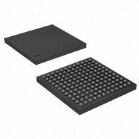
AT91SAM9R64-CU Atmel, AT91SAM9R64-CU Datasheet - Page 572

AT91SAM9R64-CU
Manufacturer Part Number
AT91SAM9R64-CU
Description
MCU ARM9 64K SRAM 144-LFBGA
Manufacturer
Atmel
Series
AT91SAMr
Specifications of AT91SAM9R64-CU
Core Processor
ARM9
Core Size
16/32-Bit
Speed
240MHz
Connectivity
EBI/EMI, I²C, MMC, SPI, SSC, UART/USART, USB
Peripherals
AC'97, POR, PWM, WDT
Number Of I /o
49
Program Memory Size
32KB (32K x 8)
Program Memory Type
ROM
Ram Size
72K x 8
Voltage - Supply (vcc/vdd)
1.08 V ~ 1.32 V
Data Converters
A/D 3x10b
Oscillator Type
Internal
Operating Temperature
-40°C ~ 85°C
Package / Case
144-LFBGA
Processor Series
AT91SAMx
Core
ARM926EJ-S
Data Bus Width
32 bit
Data Ram Size
64 KB
Interface Type
2-Wire, SPI, SSC, USART
Maximum Clock Frequency
240 MHz
Number Of Programmable I/os
118
Number Of Timers
4
Maximum Operating Temperature
+ 85 C
Mounting Style
SMD/SMT
3rd Party Development Tools
JTRACE-ARM-2M, MDK-ARM, RL-ARM, ULINK2
Development Tools By Supplier
AT91SAM-ICE, AT91-ISP, AT91SAM9RL-EK
Minimum Operating Temperature
- 40 C
On-chip Adc
10 bit, 3 Channel
Controller Family/series
AT91SAM9xxx
No. Of I/o's
49
Ram Memory Size
64KB
Cpu Speed
240MHz
No. Of Timers
3
Rohs Compliant
Yes
Package
144LFBGA
Device Core
ARM926EJ-S
Family Name
91S
Maximum Speed
240 MHz
Operating Supply Voltage
1.8|3.3 V
For Use With
AT91SAM-ICE - EMULATOR FOR AT91 ARM7/ARM9
Lead Free Status / RoHS Status
Lead free / RoHS Compliant
Eeprom Size
-
Lead Free Status / Rohs Status
Lead free / RoHS Compliant
Available stocks
Company
Part Number
Manufacturer
Quantity
Price
Part Number:
AT91SAM9R64-CU
Manufacturer:
ATMEL/爱特梅尔
Quantity:
20 000
- Current page: 572 of 903
- Download datasheet (13Mb)
Figure 37-3. Picture-In-Picture Mode Support
37.3.2
6289C–ATARM–28-May-09
Memory Peripherals
Picture-in-Picture Mode: DMAC contains a picture-in-picture mode support. When this mode is
enabled, addresses are automatically incremented by a programmable value when the DMAC
channel transfer count reaches a user defined boundary.
Figure 37-3 on page 572
i m a g e _ b a s e _ a d d r e s s i n m e m o r y . A u s e r d e f i n e d s t a r t a d d r e s s i s d e f i n e d a t
Picture_start_address. The incremented value is set to memory_hole_size = image_width -
picture_width, and the boundary is set to picture_width.
Bus locking: Software can program a channel to maintain control of the AMBA bus by asserting
hmastlock for the duration of a DMAC transfer. Channel locking is asserted for the duration of
bus locking at a minimum.
Figure 37-2 on page 571
eral. There is no handshaking interface with the DMAC, and therefore the memory peripheral
can never be a flow controller. Once the channel is enabled, the transfer proceeds immediately
without waiting for a transaction request. The alternative to not having a transaction-level hand-
– Linked lists (buffer chaining) – A descriptor pointer (DSCR) points to the location
– Replay – The DMAC automatically reloads the channel registers at the end of each
– Contiguous buffers – Where the address of the next buffer is selected to be a
in system memory where the next linked list item (LLI) exists. The LLI is a set of
registers that describe the next buffer (buffer descriptor) and a descriptor pointer
register. The DMAC fetches the LLI at the beginning of every buffer when buffer
chaining is enabled.
buffers to the value when the channel was first enabled.
continuation from the end of the previous buffer.
shows the DMAC transfer hierarchy of the DMAC for a memory periph-
illustrates a memory mapped image 4:2:2 encoded located at
AT91SAM9R64/RL64 Preliminary
572
Related parts for AT91SAM9R64-CU
Image
Part Number
Description
Manufacturer
Datasheet
Request
R

Part Number:
Description:
MCU, MPU & DSP Development Tools KICKSTART KIT FOR AT91SAM9 PLUS
Manufacturer:
IAR Systems

Part Number:
Description:
DEV KIT FOR AVR/AVR32
Manufacturer:
Atmel
Datasheet:

Part Number:
Description:
INTERVAL AND WIPE/WASH WIPER CONTROL IC WITH DELAY
Manufacturer:
ATMEL Corporation
Datasheet:

Part Number:
Description:
Low-Voltage Voice-Switched IC for Hands-Free Operation
Manufacturer:
ATMEL Corporation
Datasheet:

Part Number:
Description:
MONOLITHIC INTEGRATED FEATUREPHONE CIRCUIT
Manufacturer:
ATMEL Corporation
Datasheet:

Part Number:
Description:
AM-FM Receiver IC U4255BM-M
Manufacturer:
ATMEL Corporation
Datasheet:

Part Number:
Description:
Monolithic Integrated Feature Phone Circuit
Manufacturer:
ATMEL Corporation
Datasheet:

Part Number:
Description:
Multistandard Video-IF and Quasi Parallel Sound Processing
Manufacturer:
ATMEL Corporation
Datasheet:

Part Number:
Description:
High-performance EE PLD
Manufacturer:
ATMEL Corporation
Datasheet:

Part Number:
Description:
8-bit Flash Microcontroller
Manufacturer:
ATMEL Corporation
Datasheet:

Part Number:
Description:
2-Wire Serial EEPROM
Manufacturer:
ATMEL Corporation
Datasheet:


